Western electric 132 a schematic

This is the 4 pages manual for western electric 132 a schematic.
Read or download the pdf for free. If you want to contribute, please mail your pdfs to info@audioservicemanuals.com.

Page: 1 / 4
left right
western electric 132 a schematic

Extracted text from western electric 132 a schematic (Ocr-read)


Page 1

Warm Electric Company
No. | 32-A AMPLIFIER

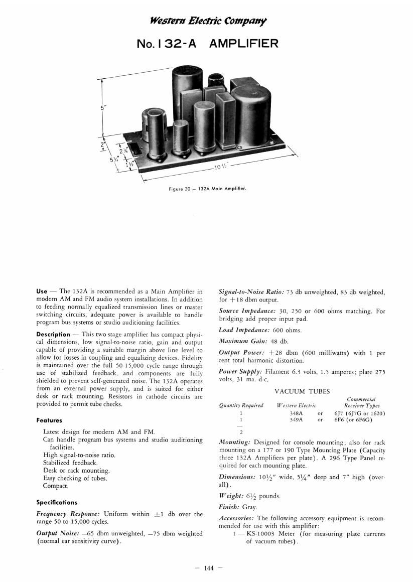
Figure 30 - l32A Main Amplifier.

Use 7 The 132A is recommended as a Main Amplifier in
modern AM and FM audio system installations. In addition
to feeding normally equalized transmission lines or master
switching circuits, adequate power is available to handle
program bus systems or studio auditioning facilities.

Description - This two stage amplifier has compact physi
cal dimensions, low signal-to-noise ratio, gain and output
capable of providing a suitable margin above line level to
allow for losses in coupling and equalizing devices. Fidelity
is maintained over the full 50-15,000 Cycle range through
use of stabilized feedback, and components are fully
shielded to prevent self-generated noise. The 152A operates
from an external power supply, and is suited for either
desk or rack mounting. Resistors in cathode circuits are
provided to permit tube checks,

Features

Latest design for modern AM and FM.

Can handle program bus systems and studio auditioning
facilities.

High signal-to-noise ratio.

Stabilized feedback.

Desk or rack mounting.

Easy checking of tubes,

Compact.

Specificalions

Frequency Response: Uniform within :1 db over the
range 50 to 15,000 cycles.

Output Noise: -65 dbm unweighted, -75 dbm weighted
(normal ear sensitivity curve).

Signal-to-Naise Ratio: 7} db unweighted, 33 db weighted,
for +18 dbm output.

Source Impedance: 30, 250 or 600 ohms matching. For
bridging add proper input pad.

Load Impedance: 600 ohms.

Maximum Gain: 48 db.

Output Power: +28 dbm (600 milliwatts) with 1 per
cent total harmonic distortion,

Power Supply: Filament 6.3 volts, 1.5 amperes; plate 275
volts, 31 ma, d-c.

VACUUM TUBES
Commfrcia/
Retainer Type;
617 (6J7G or 1620)
6% (or 61:66)

"9 tier/1 Electric

348A or
349A or

Quantity Required

N|-

Mounting: Designed for console mounting; also for rack
mounting on a 177 or 190 Type Mounting Plate (Capacity
three 132A Amplifiers per plate). A 296 Type Panel re~
cluired for each mounting plate.

Dimensions: 101/2 wide, 51A, deep and 7 high (over-
all).

lV/eigbl: 61/2 pounds.

Finish: Grayi

Accessories: The following accessory equipment is recom-
mended for use with this amplifier:

1 iKS-10003 Meter (for measuring plate currents
of vacuum tubes).

7 144 r'