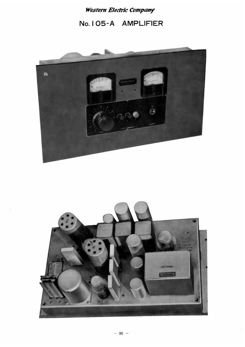
Western electric 105 a schematic

This is the 6 pages manual for western electric 105 a schematic.
Read or download the pdf for free. If you want to contribute, please mail your pdfs to info@audioservicemanuals.com.

Page: 1 / 6
left right
western electric 105 a schematic

Extracted text from western electric 105 a schematic (Ocr-read)


Page 1

Western Hectric Company
No. l 05-A AMPLIFIER

Page 2

néwwmnvlflbanichnqnnyr
No. | 05-A AMPLIFIER

NO. 105H AMPLIFIER

Apparatus List

Deaignation No. Apparatus
T1 285L Input Transformer
T2 185A Output Transformer
T3 360C Transformer
L1,L2 221R Retardation Coils
L3 221A Retardation Coil
CB Dh95423 Condenser, 0.1 Microfarad
CS, C6, C7 230A Condensers, 0.4 Microfarad
Cl, 08 Cornell Dubilier Corp. Type

MA-l3358-PE Electrolytic Con-
densers, 50 Microfarads, 25 Volt
D-C. Working Voltage

2 Cornell Dubilier Corp. Type

2 MA-l3257-PE Electrolytic Con-

O.2 densers, 8-8 Microfarads, 450
Volts D-C. Working Voltage

C4 Cornell Dubilier Corp. Type
MA-l3438-PE Electrolytic Con-
denser, lOO Microfarads, 12
Volts DLC. Working Voltage

011 Cornell Dubilier Corp. Type
1W3Sl Cbnd. .OlMF

R17 18GF Resistances - 800 - Ohms

R18.1, R18.2 19FG Resistances- 100-100 Ohms

R19.l, R19.2

International Resistance Company
pre BT-l Resistances

R1 100,000 Ohms at 10%
R2 4,000 Ohms i 5%
R4 60,000 Ohms * 10%
R6 0.5 Megohm i 10%

All apparatus is Western Electric unless otherwise
specified.

ESL-611824.3heet 1, Issue 2
Printed in U.S.A. Sheet 1 of 3 Sheets

792,