Western electric 101 f brochure

This is the 6 pages manual for western electric 101 f brochure.
Read or download the pdf for free. If you want to contribute, please mail your pdfs to info@audioservicemanuals.com.

Page: 1 / 6
left right
western electric 101 f brochure

Extracted text from western electric 101 f brochure (Ocr-read)


Page 1

«M .

BELL SYSTEM PRACTICES SECTION AB46.024
Transmission Engineering and Data Issue 2, November 1939
Vacuum Tube Data A T & 1 Co Standard

Western flecfr 'c

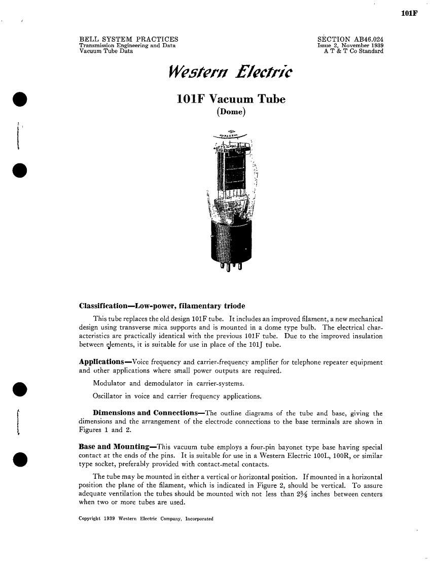
lOlF Vacuum Tube
(Dome)

Classlfication-Low-power, filamentary triode

This tube replaces the old design 10117 tube. It includes an improved filament, a new mechanical
design using transverse mica supports and is mounted in a dome type bulb. The electrical char-
acteristics are practically identical with the previous 101F tube. Due to the improved insulation
between elements, it is suitable for use in place of the 101] tube.

Applications-Voice frequency and carrier-frequency amplifier for telephone repeater equipment
and other applications where small power outputs are required.

Modulator and demodulator in carrier-systems.

Oscillator in voice and carrier frequency applications.

Dimensions and Connections-The outline diagrams of the tube and base, giving the
dimensions and the arrangement of the electrode connections to the base terminals are shown in
Figures 1 and 2.

Base and Mounting-This vacuum tube employs a four-pin bayonet type base having special
contact at the ends of the pins. It is suitable for use in a Western Electric 100L, 100R, or similar
type socket, preferably provided with contact-metal contacts.

The tube may be mounted in either a vertical or horizontal position. Ifmounted in a horizontal
position the plane of the filament, which is indicated in Figure 2, should be vertical. To assure
adequate ventilation the tubes should be mounted with not less than 2% inches between centers
when two or more tubes are used.

Copyright 1939 Western Electric Company, Incorporated

101F

Page 2

101]?

Average Direct Interelectrode Capacitances

Gridtoplate,.. ..... .. .. ..... 5.9ppf
Grid tofilament... .. , ............ . 4.2 puf
Plate to filament.... .. .. .. ..... .. . . .. 2.7 npf

These values are for a based tube without socket.

Filament Rating
Filament current. . . . . . . . . . . . . . . . .......... 0.50 ampere, d.c.
Nominal filament voltage. . . . lllll . . . ........... 4.15 volts

The filament of this tube is designed to operate on a current basis and should be operated at as
near the rated current as practicable.

The filament resistance of this tube increases slightly during the first 2000 hours of operation.
The voltage given above is the nominal value after this resistance change has stabilized.

Characteristics-Typical curves showing plate current as a function of grid voltage for several
values of plate voltage are shovvn in Figure 3. The grid and plate voltages are measured from the
negative end of the filament. Corresponding amplification factor, plate resistance and transcon-
ductance characteristics are given in Figures 4, 5 and 6 respectively. Plate current as a function
of plate voltage for several values of grid voltage is shown in Figure 7.

Operating Conditions and Output-Permissible operating plate and grid voltages are
included within the area, ABCD in Figure 3. A number of recommended and maximum operating
conditions and the corresponding values of amplification factor, plate resistance and performance
data are given in the table below. Recommended conditions or others of no greater severity should
be selected in preference to maximum conditions wherever possible. The life of the tube at maximum
operating conditions may be shorter than at less severe conditions.

The performance data shown includes the fundamental power output in milliwatts and the
second and third harmonic levels in db below the fundamental for values of load resistance equal
to the plate resistance and for a load resistance of 12000 ohms. The peak value of the sinusoidal
input voltage Em, which gives the indicated output Pm, and harmonic levels Fm and Fm, in
each case is numerically equal to the grid bias. For a smaller input voltage E3, the approximate
levels may be computed from the following relations:

Eg 2
P = new)

E12m

F2 = F2111 + 2010;!10 E-
3

F3 = F3m + 40 logm E

Microphonic Noise

For a plate voltage of 130 volts, a grid bias of -8 volts, and a load resistance of 100,000 ohms,
the mean microphonic output level of this tube, measured in a laboratory reference test set is 30 db
below 1 volt. The range oflevels ofindividual tubes extends from 20 to 40 db below 1 volt. Since
microphonic noise output depends on the type and intensity of the mechanical disturbance which
produces it, the values given here are useful chiefly for comparison with the levels of other types
of tubes which have been tested in the same way.

[2]