Western electric 60 a schematic

This is the 4 pages manual for western electric 60 a schematic.
Read or download the pdf for free. If you want to contribute, please mail your pdfs to info@audioservicemanuals.com.

Page: 1 / 4
left right
western electric 60 a schematic

Extracted text from western electric 60 a schematic (Ocr-read)


Page 1

WWI-n Hectfic Company
No.60-A AMPLIFIER

NO. 2444 ) No. 205-0
VACUUM TUB VACUUM TUBES

' FlLAME NT
RH EC STAT

GAIN @ PLATE CURRENT
CONTROL JACK.TUBE v3
PLATE CURRENT J FILAMENT
V CURRENT JACK

PLATE CURRENT
JACK. TUBE v2

JACK.TUBE VI

AMPLIFIER
No. 60-A

[mtructz'om for U re

The No. (SO-A Amplifier is primarily designed for use in Western Electric
Speech Input Equipments for radio telephone broadcasting or similar service.
It is capable of amplifying low-level audio frequency signals to such a level that
they may be fed into a radio transmitter or telephone line. It can also be used
for operating loud speakers.

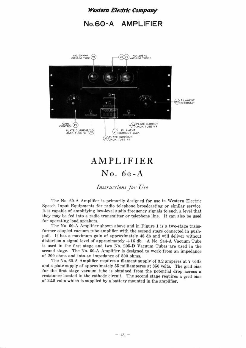
The No. GO-A Amplifier shown above and in Figure 1 is a two-stage trans-
former coupled vacuum tube amplifier with the second stage connected in push-
pull. It has a maximum gain of approximately 48 db and will deliver without
distortion 3. signal level of approximately +16 db. A No 244-A Vacuum Tube
is used in the first stage and two No. 205-D Vacuum Tubes are used in the
second stage, - The No. 60-A Amplifier is designed to work from an impedance
of 200 ohms and into an impedance of 500 ohms.

The No. 60-A Amplifier requires a filament supply of 3.2 amperes at 7 volts
and a plate supply of approximately 55 milliamperes at 350 volts. The grid bias
for the first stage vacuum tube is obtained from the potential drop across a
resistance located in the cathode circuit. The second stage requires a grid bias
of 22.5 volts which is supplied by a battery mounted in the amplifier.

_43_

Page 2

Western Electric Company
No.60-A AMPLIFIER

FIRST STAGEGRID @
BIAS RESISTANCE FIRST STAGE FILAMENT
SECO DST GE CIRcoIT RESISTANCE
N A
FIRST STAGE PLATE M 7 FIRST STAGE VACUUM
CIRCUIT FILTER vegggmg (VS' TUBE SOCKET
,_A,

INDUCTANCE fax
r\ (RI FIRST STAGE PLATE
KLI/ FEED REsISTANCE

R
R ESISTANCE

P|>GAIN CONTROL

\V, POTENTIDMETER

" FIRST STAGE

C4)FLATE CIRCUIT
FILTER

\71 CCNDENSERS

' I
1 SECOND STAGE I6}; SECOND STAGE
it

FILAMENTIRS!

RHEOSTATIV I CRIo BATTERY -. [NWT TRANSFORMER

I

SEcoNo STAGE ,L ,i FIRST STAGE
PLATE CIRCUIT {.2}; (CSI PLATE CIRCUIT
INoucTAch ~ \JaLocRINo CONDENSER
OUTPUT (TaVCZ PFLiTg Sir/:55
TRANSFORMEnxJ \V BVEPASS CONDENSER

Fig. I-No. 60-A Amplifier-Rear View

The component parts of the No. 60-A Amplifier are mounted on a panel
19 inches wide and 83/4r inches high designed for relay rack mounting. The
vacuum tubes are mounted in a recess in the panel and, together with the jacks,
gain control and filament rheostat are accessible from the front. The other
apparatus is mounted on the rear of the panel and is protected by a removable
dust cover.
DESCRIPTION

The schematic circuit diagram of the N0. 60-A Amplifier is shown in Figure
2 and the wiring diagram in Figure 3. The signal is applied to the grid of
vacuum tube V1 through the input transformer T1 which is designed to work
from a ZOO-ohm circuit into the grid of a vacuum tube. The secondary of the
input transformer is shunted by a potentiometer P1, the variable arm of which
is connected directly to the grid of the tube. This potentiometer is divided into
23 steps of 3 db each. As it is advanced from step zero the gain of the amplifier
is increased in 3 db steps from a loss of 18 db on step Not 1 to a gain of 48 db on
step No. 23.

The first stage is coupled to the second stage by means of the interstage
transformer T2. The plate current for the first stage vacuum tube is supplied
through the resistance R1. A condenser C3 connected between the primary of
the transformer and the cathode circuit prevents direct current from flowing

_44,