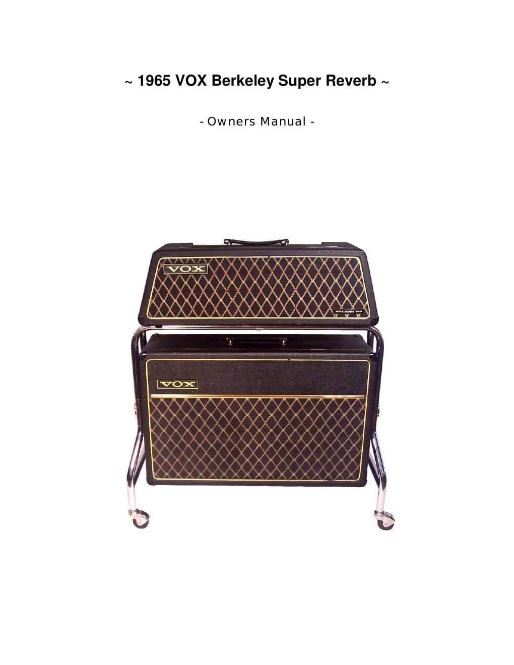
Vox berkeley super reverb twin owners manual schematic

This is the 10 pages manual for vox berkeley super reverb twin owners manual schematic.
Read or download the pdf for free. If you want to contribute, please mail your pdfs to info@audioservicemanuals.com.

Page: 1 / 10
left right
vox berkeley super reverb twin owners manual schematic

Extracted text from vox berkeley super reverb twin owners manual schematic (Ocr-read)


Page 1

1 Contents: Warnings -“ Dos and Donts -¦-¦-¦-¦-¦-¦-¦-¦-¦-¦-¦-¦-¦-¦-¦.Pages 1, 2 Part Numbers and other Information -¦-¦-¦-¦-¦-¦-¦-¦-¦-¦-¦. Page 2 Mirror Image of Bottom View of Amp Chassis and Tubes -¦-¦. Page 3 Factory Chassis Layout -¦-¦-¦-¦-¦-¦-¦-¦-¦-¦-¦-¦-¦-¦-¦-¦... Page 4 Factory Schematic Diagram -¦-¦-¦-¦-¦-¦-¦-¦-¦-¦-¦-¦-¦-¦-¦ Page 5 Factory Parts List -¦-¦-¦-¦-¦-¦-¦-¦-¦-¦-¦-¦-¦-¦-¦-¦-¦-¦-¦.. Pages 6, 7 An Article about the Amp from the Web .-¦-¦-¦-¦-¦-¦-¦-¦-¦... Page 8 Photos of the Amp -¦-¦-¦-¦-¦-¦-¦-¦-¦-¦-¦-¦-¦-¦-¦-¦-¦-¦-¦. Page 9

Page 2

1 Warnings -“ Dos and Donts -“ Always use, and fully tighten, the head clamp to the trolley so the head doesnt slide off. -“ Always plug in the speaker cable at each end before plugging in AC power cord. -“ Nev er turn on any tube Amp unless the speaker cable is hooked up; If you dont, youll blow the output section of the AMP. (This includes combos too.) -“ To unplug the speaker cable, slide the blue release, on the XLR connector, away from you. -“ Dont pick up the speaker cabinet by the top of the trolley. (The chrome stand) The trolley is designed to come apart just abov e the hand nuts. -“ To remove trolley: 1 -“ Remov e Amp Head, and loosen the trolleys hand nuts a little. 2 -“ Pull up on one side of trolley, and pull that side along the bottom half with the top half down ev en to where it was, but along side. 3 -“ Pull up on the other side to remov e top half of trolley. 4 -“ Put speaker cabinet on chair, and remov e hand nuts and remove lower trolleys. When reassembling, always put the brown face of the large washers, inside the hand nuts, towards the speaker cabinet. WARNING READ CAREFULLY!!!! Older electrical equipment often has a HOT chassis with no modern AC Power plug. This means that its possible to plug in the amp the wrong way and touch another electrical device, like your PA system, and get a belt of 110 Volts AC. I did this in the old days and saw blue lights before I passed out! After that, I always held the guitar strings with one hand, wet my finger a little, and then quickly taped the mike, or other equipment. Now days I use a v olt meter. The new power cords, with one prong larger then the other, prev ents this. Your Amp has the original power cord; I put a white sticker on one side; always plug in the amp with the sticker UP as in the picture to the left. Also, always keep the polarity (Line Rev erse) switch to the LEFT as shown below. If the power cord is replaced with a new one, the Line Rev erse switch should hav e the unused lead cut off from the switch. WARNING: Only a qualified technician should work on tube amps. The big can capacitor C-26, see page 3, is actually three Caps in one: C-26A = 270 Volts DC, C26B = 240 Volts DC, and C26C = 150 Volts DC. With the Amp off these caps stay charged which means that if you touch the terminals of C26 your guitar playen days are ov er. Note that these terminals run to every tube socket, and else ware, so you could get electrocuted there too. The first thing a tech does before working on an amp is to discharge these capacitors through a high power resistor, and then shunt all C26 terminals to ground; these pesky little devils have a way of recharging, memory, and still get ya. ALWAYS KEEP LINE SWITCH SW-2 TO THE LEFT AS SHOWN