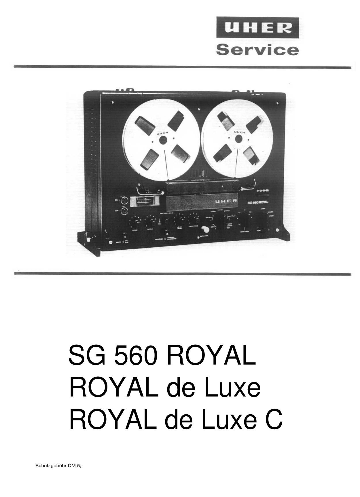
Uher Royal Deluxe Service Manual

This is the 24 pages manual for Uher Royal Deluxe Service Manual.
Read or download the pdf for free. If you want to contribute, please mail your pdfs to info@audioservicemanuals.com.

Page: 1 / 24
left right
Uher Royal Deluxe Service Manual

Extracted text from Uher Royal Deluxe Service Manual (Ocr-read)


Page 1

I nhaltsverzeichnis Die Erläuterungen der einzelnen Kapitel sind i n sich abgeschlossen. Ein Studium der ge- samten Anleitung ist damit nicht erforderlich. Selbstverständlich resultieren daraus, bei chronologischer Betrachtung, einige Wieder- holungen. 1.0 Ausschwenken des Gerätes aus dem Gehäuse und entfernen des Auflegers 1 1.1 Antrieb 1 1.2 Kupplungen 4 1.3 Prüfung und Einstellung der Fühlhebel 5 1.4 Prüfung und Einstellung des Bandzugkomparators 6 1.5 Prüfung und Einstellungdes Vor-Rücklaufes 7 1.6 Prüfung und Einstellung der Aufwickelkupplung 1.7 Prüfung und Einstellung der Bremsen 9 1.8 Austausch der FYiktionsräder und der Antriebsriemen 9 1.9 Prüfung und Einstellung des Bandgeschwindigkeitswählers 10 2.0 Austausch des Reibrades 11 2.1 Prüfung und Einstellung des Druckes der Andruckwelle an die Tonwelle 1 2 2.2 Schnellstop 12 2.3 Bandführungen 13 2.4 Kopfträger 13 2.5 Prüfung und Einstellung der Kontaktfedersätze und Schalter 15 2.6 Schmierung und Wartung 2.7 Technische Daten Contents Each chapter of this manual provides com- plete Information an the topic covered. Thus, it will not be necessary to study the entirebooklet. As a result of this construction of the manual, you will discover a few repeats when studying more than one chapter. 1.0 Swinging the Recorderfrom its Caseand removing depositor 1 1.1 Transport Mechanicm 1 1.2 Clutches 4 1.3 Checking and Adjustingthe Sensing Levers 5 1.4 Checking and Adjusting the Tape Tension Comparator 6 1.5 Checking and Adjusting the Fast Forward and Rewind Functions 7 1.6 Checking and Adjusting 8 the Wind-on Clutch 8 1.7 Checking and Adjusting the Brakes 9 1.8 Replacing the Friction Wheelsand Driving Belts 9 1.9 Checking and Adjusting the Tape Speed Selector 10 2.0 Replacing the Idler 11 2.2 2.3 2.4 2.5 Checking and Adjusting the Pressure Between the PressureRoller and the Capstan Rapid Stop Tape Guides Head Support Assembly Checking and Adjusting the ContactSpring Assemblies and Switches 16 2.6 Lubrication and Maintenance 16 2.7 Technical Data 12 12 1 3 13 15 16 16 Sommaire Dans las präsentes instructions, chaque chapitre constitue en lui-müme un tout in- däpendant et peut donc ätre consultä säparä- ment, seien las travaux ä exäcuter sur le magnätophone. II s'ensuit que, de chapitre en chapitre, certaines räpätitions sont inävi- tables. 1.0 Extraction du magnätophone hors de son coffret et dämontage de la plaque de recouvrement 1 1.1 Mäcanisme d'entrainement 1 1.2 Embrayages 4 1.3 Contröle et räglagedes leviers palpeurs 5 1.4 Contröle et räglage du comparateur de traction 6 1.5 Contröle et räglage du dMilement accälärä en avant et en arriäre 7 1.6 Contröle et räglage deI'embrayage enrouleur 8 1.7 Contröle et räglage des freins 9- 1.8 Echange des roues ä friction et des courroies 9 1.9 Contröle et räglage du sälecteur de vitesses 10 2.0 Echange de la reue ä friction du sälecteur de vitesses 11 2.1 Contröle et räglage de la pression du galet sur le cabestan 12 2.2 Arret instantanä de la bande magnätique 12 2.3 Guide-bande 1 3 2.4 Tätes magnätiques 13 2.5 Contröle et räglage des jeux de lames de Contact et des commu- tateurs de correction ä la lecture 1 5 16 2.6 Lubrification et entretien 2.7 Caractäristiques techniques 1 6 Anhang für die Geräte UHER Royal de Luxe und UHER Royal de Luxe C. 1.0 Ausschwenken des Gerätes aus dem Gehäuse 18 1.85 Austausch des Antriebsriemens zum Bandzählwerk 18 2.23 Prüfung des mechanischen Schnellstops 19 2.24 Einstellung des mach. Schnellstops 19 2.25 Einstellung des Schnellstops 20 2.32 Einstellung der Bandführung 20 2.7 Technische Daten 21 2.71 Daten des Verstärkers 22 Appendix for the units UHER Royal de Luxe and UHER Royal de Luxe C 1.0 Swinging the Recorderfrom its Case 1.85 Replacing the Driving Beit for the Digital Counter 2.23 Checking the Mechanical Rapid Stop 2.24 Adjusting the Mechanical Rapid Stop 2.25 Adjusting the Rapid Stop 2.32 Adjusting the Tape Guide 2.7 Technical Data 2.71 Amplifier Data 18 18 19 19 20 20 21 22 Annexe pour las magnätophones UHER Royal de Luxe et UHER Royal de Luxe C 1.0 Extraction du magnätophone hors de son coffret 18 1.85 Echange de la courroie d'entrainement du compteur 18 2.23 Contröle de l'arr6t instantanä mäcanique 2.24 Räglage de I'arrät i nstantanä mäcanique 2.25 Räglage de I'arret instantanä 2.32 Räglage des guide-bande 2.7 Caractäristiques techniques 2.71 Caractäristiques de 1'amplificateur 19 19 20 20 21 22

Page 2

1.0 Ausschwenken des Gerätes aus dem Gehäuse und entfernen des Auflegers Um die Servicearbeiten auszuführen, wird das Gerät aus dem Gehäuse herausge- schwenkt bzw. der Aufleger entfernt. a) Gerät herausschwenken: Die 2 großen Befestigungsschrauben des Auflegers herausschrauben. Jetzt das Ge- rät aus dem Gehäuse herausschwenken und abstützen bzw. auf eine Seite stellen. b) Aufleger entfernen:Vordere Tonkopfkappe und sämtliche Be- dienungsknöpfe abziehen. Die 8 Befesti- gungsschrauben des Auflegers heraus- schrauben und Aufleger entfernen. 1.1 Antrieb (siehe Abb. 1) Der Bandgeschwindigkeitswähler schaltet gleichzeitig den Netzschalter und die zur Bandgeschwindigkeit gehörende Entzerrung ein. Die Umschaltung der Bandgeschwindig- keit bewirkt ein Verstellen des Reibrades ' B), das in die jeweiligen Stufen der Motor rolle ( A) und der Schwungmasse (C) ein- greift. I n Stellung -žVerstärker" des Bandgeschwin- digkeitswählers wird der Motor abge- schaltet. Die Besonderheit des Antriebssystemes er- möglicht den Betrieb des Gerätes in horizon- taler und vertikaler Lage. Die nötige Voraus- setzung dazu bringt der Aufbau der Kupplun- gen in Verbindung mit den Fühlhebeln. Diese Anordnung, die bei allen Betriebsarten und i n allen Betriebsstellungen wirksam ist, wird als -žBandzugkomparator" bezeichnet.Zum Verständnis der Arbeitsweise des Band- zugkomparators ist zunächst der Aufbau der Kupplungen zu betrachten (siehe auch Abs. 1.2). Da beide Kupplungen gleichartig aufgebaut sind, genügt die Beschreibung einer Kupplung. 1.0 Swinging the recorder from its case and removing depositor For the purpose of carrying out service work, the unit is swung out from the case or the depositor removed. (a) Swinging out the recorder: Unscrew the two large fixing screws. Now swing out the unit from the case and support it or place it an one side. (b) Removing the depositor: Pull off front sound-head cap and all con- trol knobs. Unscrew the eight fixing screws of the depositor and remove de- positor. 1.1 Transport Mechanism (see Fig. 1) The tape speed selector at the same time switches an the mains switch and introducesthe proper equalization automatically. Changing over the tape speed causes a change in the position of the friction wheel (B), which engages in the respective steps of the motor pulley (A) and the flywheel (C). I n the position "Amplifier" of the tape speed selector, the motor la disconnected. The special design of the transport mecha-nism allows the recorder to be operated in a horizontal as well es in a vertical position. This fact is due to the design of the clutches which operate in cooperation with the sen- sing levers. This arrangement which is effec- tive during all modes of operation of the re- corder, is called the "Tape Tension Com- parator". For the better understanding of the function- i ng of the tape tension comparator, we first discuss the design of the clutches (see also paragraph 1.2). Since the two clutches are of identical design, it will suffice to describe one of them. 1.0 Extraction du magnetophone hors de son coffret et dämontage de la plaque de recouvrement Pour I'execution des travaux de räglage et d'entretien, il est näcessaire d'extraire le magnetophone hors de son coffret ou de re- tirer la plaque de recouvrement. a) Extraction du magnetophone: Dägager [es deux grosses via de fixation de la plaque de recouvrement. Sortir le magnetophone hors de son coffret et le poser sur une de ses faces. b) Demontage de la plaque de recouvrement: Retirer la coiffe avant des tätes magne- tiques et tous las boutons de commande. Detacher la plaque de recouvrement apräs le desserrage de ses huit via de fixation. 1.1 Mecanisme d'entrainement (voir fig. 1) Uactionnement du selecteur de vitesses pour le choix d'une des vitesses de däfilement met en meme temps le magnetophone sous tension, c'est-ä-dire enclenche le commuta- teur du secteur et le reseau correcteur cor- respondant ä la vitesse de däfilement regläe. Le räglage de la vitesse de däfilement sur la valeur voulue deplace la roue ä friction (B) qui s'engage dans le gradin respectif de la poulie (A) et du volant (C). En position -Amplificateur- du selecteur de vitesses, le moteur d'entrainement est deconnecté. Le magnetophone peut travailler aussi bien en position horizontale qu'en position verti- cale, gräce ä la nouvelle conception du mecanisme d'entrainement avec embrayages speciaux et leviers palpeurs. Ce mecanismeexträmement sensible, appele -comparateur de traction-, est efficace dans toutes les positions et pour tous las modes opäratoires. Pour comprendre plus facilement le principe du comparateur de bande, il convient tout d'abord d'etudier la structure des embraya- ges (voir sous 1.2). Las deux embrayages etant identiques, un seul sera dächt ci- apräs. SG 560 Roya

Page 5

1.14 Rücklauf (siehe Abb. 3) Von einem Hebelwerk wird das von der Mo- torrolle (A) über den Riemen (D) getriebene Friktionsrad (E) gegen die Druckscheibe (0) gedrückt. Gleichzeitig wird die Bandzugstange (S) in Pfeilrichtung bewegt. Dadurch wird die Komparatorfeder (K) vorgespannt, die Kom- paratorfeder (L) entspannt und die Bremse ( Q) von der Druckscheibe (0) abgehoben. Die Bremse (P) dagegen sperrt die Druck- scheibe (G) in ihrer gewollten Drehrichtung. Durch die vorgespannte Komparatorfeder (K) wird über den Fühlhebel (H) und dem Winkel- hebel (N) ein so großer Druck auf die Druck- scheibe (0) übertragen, daß das Mitnahme- moment genügend groß wird, um die volle Umspulkraft vom Friktionsrad (E) zu über- nehmen. Der Fühlhebel (H) sorgt nunmehr dafür, daß die für den Umspulvorgang be- nötigte Kraftübertragung in gleicher Größe erhalten bleibt. Durch die entspannte Komparatorfeder (L) wird über den Fühlhebel (I) und den Druck- winkel (M) ein geringer Druck auf die Druck- scheibe (G) übertragen. Der Fühlhebel (I) sorgt jetzt dafür, daß mit dem sich ändernden Bandwickeldurchmesser der abwickelnden Kupplung deren Brems- moment geregelt und damit der Bandzug kon- stant gehalten wird. Beim Abschalten der Stellung ,.Rücklauf" bleibt das Tonband stehen, weil die fördernde Kraft des Friktionsrades (E) aufgehoben wird und die rechte gesperrte Druckscheibe (G) die Kupplungsscheibe abbremst. 1.14 Rewind (see Fig. 3) The friction wheel (E) which is driven by the motor pulley (A) via the belt (D) is pressed against the thrust disk (O) by means of a l ever system. Simultaneously, the tape ten- sion rod (S) is moved in the direction of the arrow. In this manner the comparator spring (K) is being pretensioned, the comparator spring (L) is being relaxed and the brake (Q) i s lifted from the thrust disk (0), whereas the brake (P) blocks the rotation of the thrust disk (G). Due to this pretensioned stat6 of the comparator spring (K), a force is exerted via the sensing lever (H) and the angular thrust lever (N) onto the thrust disk (0) which makes the friction within the clutch great enough to enable the clutch to transmit the entire rewinding torque provided by the fric- tion wheel (E). The sensing lever (H) keepsthe rewinding torque constant. Due to the relaxed state of the comparator spring (L) only a small force is exerted an the thrust disk (G) via the sensing lever (I) and the angular thrust lever (M). The sensing lever (I) controls the braking ac- tion of the pay-out clutch as a function of the diameter of the tape roll and thus keeps the tape tension constant. When disconnecting in position "Rewind", the tape stops, since the driving force of friction pulley (E) is cancelled and the right- hand blocked pressure disk (G) brakes the clutch disk. - 1.14 Regime .Defilement accelere arriere- (voir fig. 3) Un systeme de leviers presse la roue a fric- tion (E) - entrainee par la poulie (A) du moteur et par la courroie (D) - contre le plateau presseur (0). En meme temps, la barre de traction (S) est deplacee dans le sens de la fleche. A la suite de ce mouve- ment, le ressort (K) est tendu, le ressort (L) se detend et le frein (Q) du plateau presseur ( 0) se souleve. Le frein (P) bloque par con-tre le plateau presseur (G) dans le sens de rotation spontane. Par I'intermädiaire du le- vier palpeur (H) et du levier coude (N), le ressort tendu (K) transmet une si grande force sur le plateau presseur (0), que le couple d'entrainement est süffisant pour reprendre le plein effort de bobinage de la roue a friction (E). Le levier palpeur (H) dose alors la force necessaire a transmettre pour l e reembobinage de la bande. Le ressort (L) etant detendu, il ne transmet qu'une faible force sur le plateau presseur(G) par I'intermediaire du levier palpeur (I) et du levier coudä (M). A son tour, le levier palpeur (I) dose le couple de freinage de I ' embrayage derouleur en fonction de la l ongueur de bande encore disponible sur la bobine, ce qui stabilise la traction exercee sur la bande. A I'arrät du -Defilement accelere arriere-, la bande magnetique s'immobilise, du fait que l a force motrice de la roue a friction (E) est supprimee et que le plateau presseur drolt ( G) bloquä freine le disque d'embrayage. 1.2 Kupplungen (siehe Abb. 4) I m Aufbau der Kupplungen besteht kein Unterschied. Sie setzen sich aus folgenden Teilen zusammen: A Spulenteller B Mitnehmerstift C Beilagscheibe D Oberes Kugellager E Chassis F Unteres Kugellager G Kupplungsscheibe H Sternfeder 1.2 Clutches (see Fig. 4) The two clutches are of identical design. Each clutch consists of the following parts: A Turntable B Driving pin C Shim plate D Upper ball bearing E Chassis F Lower ball bearing G Clutch disk H Star-shaped spring 1.2 Embrayages (voir fig. 4) Les deux embrayages ont une structure iden- tique et se composent des pieces suivantes: A Plateau de bobine B Broche d'entrainement C Rondelle d'epaisseur D Roulement ä billes superieur E Cage F Roulement a billes inferieur G Disque d'embrayage H Ressort etoile SG 560 Royal 4

Page 19

Ausgangsleistung an 4 Ohm Sinus Dauerton: 2x10Watt Leistungsbandbreite: 20-14 000 Hz (bei 1 % Klirrfaktor) Übersprechdämpfung: >60 dB Fremdspannungsabstand: Pegel I bei 50 mW > 64 dB Pegel II bei 50 mW >_ 69 dB bei 10 W > 75 dB (bei Mindestein- gangspegel nach DIN 45 500) Balance: jeder Kanal kann auf Null eingestellt werden Höhen: + 14 dB bis -16 dB Tiefen: + 16 dB bis - 19 dB Klirrgrad: < 0,5 % (bei Nennleistung 1 kHz) Alle Daten werden entsprechend den durch die deutschen Normen (DIN) festgelegten Meßvorschriften für Magnettongeräte ange- geben. Output power across 4 Ohm sinusoidal continuous tone: 2x10W Power bandwidth: 20 to 14,000 Hz ( with 1 % harmonic distortion) Crosstalk attenuation: 60 dB S/N ratio unweighted: l evel I at 50 mW > 64 dB l evel II at 50 mW >_ 69 dB at10W>75dB (with minimum input level to DIN 45 500) Balance: each channel can be set to zero Treble: +14 dB to-16 dB Bass: +16 dB to -19 dB Non-linear distortion: < 0.5 0 % (at nominal output 1 kHz) All data are stated in accordance with the measuring specification for magnetic tape recorders laid down in the German industrial standards (DIN). Puissance de sortie: 2 x 10 watts ä 4 ohms en regime sinusoidal continu Bande passante: 20 ä 14 000 Hz (ä une distorsion harmonique 1 % ) Affaiblissement diaphonique: >60dB Rapport signal/bruit: Niveau I > 64 dB ä 50 mW Niveau II >_ 69 dB ä 50 MW>_ 75 dB ä 10 W (au niveau d'entree minimal, conforme ä la norme DIN 45 500) Balance de räpartition sonore: l e volume acoustique de chaque canalpeut ätre räglö sur 0 dB Plage de correction des aigus: de -1-14 dB ä -16 dB Plage de correction des graves: de +16 dB ä -19 dB Distorsion harmonique: < 0,5 (ä la puissance nominale et 1 kHz) Toutes les caracteristiques techniques ont ete däterminäes selon [es mäthodes de me-sure prescrites pour les magnetophones par l es normes allemandes DIN. Die Serviceanleitung für das Gerät UHER SG 560 Royal gilt auch für die Geräte UHER Royal de Luxe und UHER Royal de Luxe C. Die Abs. 1.0, 1.85, 2.23, 2.24, 2.25, 2.7 und 2.71 weichen wie folgt ab: 1.0 Ausschwenken des Gerätes aus dem Gehäuse (siehe Abb. 21) Um die Servicearbeiten auszuführen, wird das Gerät folgendermaßen aus der Holzzarge herausgeschwenkt: Befestigungsschrauben (A) des Traggriffes (B) entfernen. Die nun zugänglich geworde- nen Gewindebuchsen (C) lösen und das Ge- rät in Pfeilrichtung aus der Holzzarge heraus- schwenken. 1.85 Austausch des Antriebsriemens zum Bandzählwerk Zum Austausch des Antriebsriemens sind zweckmäßigerweise die Bedienungsknöpfe und die Abdeckplatte zu entfernen. Dann kann der Antriebsriemen aus der Laufrille des Antriebsrades am Bandzählwerk gehoben werden. Mit einer Pinzette läßt sich nunmehr der Riemen aus der Laufrille im Spulenteller herausziehen. Der Einbau ist sinngemäß in umgekehrter Reihenfolge vorzunehmen. The Service Instruction for the model UHER SG 560 Royal also applies to the models UHER Royal de Luxe and UHER Royal de Luxe C. The paragraphs 1.0, 1.85, 2.23, 2.24, 2.25, 2.7 and 2.71 differ as follows: 1.0 Swinging the Recorder from its Case (see Fig. 21) For the purpose of carrying out service werk,the unit is swung out from the wooden frame as follows:Remove fixing screws (A) of carrying handle (B). Slacken the threaded sockets (C), which have now become accessible and swing outthe unit from the wooden frame in the direc-tion of the arrow. 1.85 Replacing the Driving Belt for the Digital Counter I n order to replace the driving belt for the digital counter, we recommend removing the control knobs and the cover plate. Then,the driving belt can be lifted from the groove of the drive wheel of the counter mechanism. Pull the belt out of the groove of the turn- table using a pair of tweezers. Install the new belt in reverse order. Les instructions d'entretien et de röglage du magnötophone UHER SG 560 Royal sont valables ägalement pour les types UHER Royal de Luxe et UHER Royal de Luxe C, ä I'exception des paragraphes 1.0, 1.85, 2.23,' 2.24, 2.25, 2.7 et 2.71: 1.0 Extraction du magnötophone hors de son coffret (voir fig. 21) Pour I'execution des travaux d'entretien et de räglage, le magnötophone doit ätre ex- trait de son coffret de la fag;on suivante:Degager les vis de fixation (A) de la poignee(B). Apräs le dämontage de la poignäe, des-serrer I'ecrou (C) devenu accessible ei sortir l e magnötophone hors du coffret dans le sens de la fleche. 1.85 Echange de la courroie d'entrainement du compteur Pour I'echange de cette courroie, il est re- commandä de dämonter auparavant [es bou- tons de commande et la plaque de recouvre- ment. Sortir la courroie hors de la gorge de l a reue d'entrainement du compteur, puis avec des pincettes, hors de la gorge de rou- l ement du plateau de la bobine. Proceder au remontage dans ('ordre de suite inverse. SG 560 Royal ROYAL DE LUXE ROYAL DE LUXE C 1 8