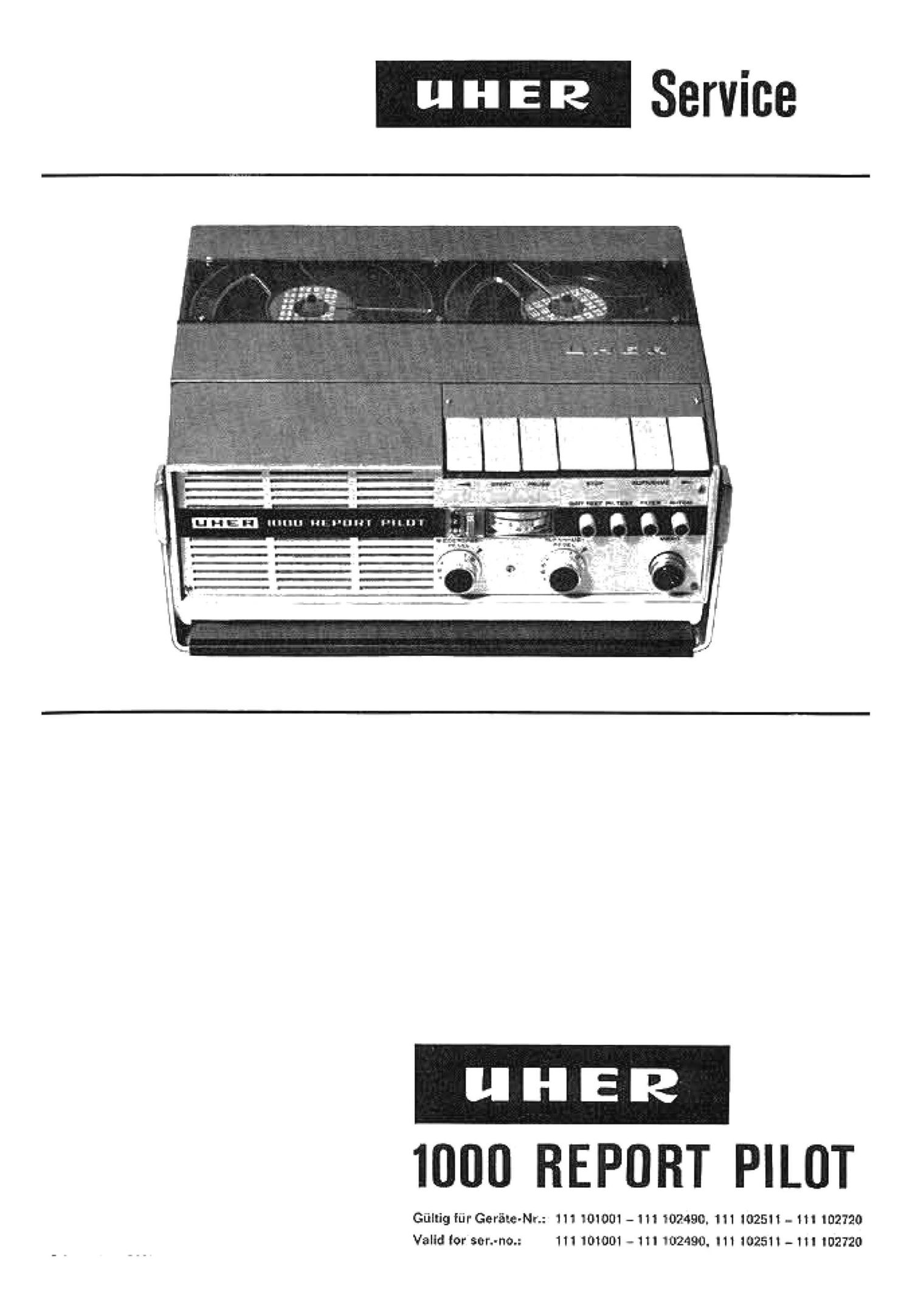
Uher 1000 Report Pilot Service Manual

This is the 30 pages manual for Uher 1000 Report Pilot Service Manual.
Read or download the pdf for free. If you want to contribute, please mail your pdfs to info@audioservicemanuals.com.

Page: 1 / 30
left right
Uher 1000 Report Pilot Service Manual

Extracted text from Uher 1000 Report Pilot Service Manual (Ocr-read)


Page 1

Service

1000 REPORT PILOT

Gfilfig fLirGerfileer's 111 101001 -111 $02490. H1 1025 - 111 102720
Valid [or urn-nos 111 101001 - HI 102490. I11 102511 -11l 102720

Page 2

MLTSVEBZEICI'WIS

Selto
LMedtlnlmherTelI . . . . . . 1
1.1 Leaf-work .......... 1
amen-niacin '
and finitellungen . . .\ ...... 2
2.1 Kupplungen ......... 2
2.2 Bremeen .......... 4
23 Fordelzug .......... 5
2.4 Bremelcreit doe Andruddilzee . . B
2.5 Elnewilen deg Stopreleie . . . . 6
2.6 Sch neller Vor-Htickleuf ..... 7
2.7 Bandftihrung ......... B
2.5 Prflfung tier Sdmungmeeee 8
2.9 Auewedieeln dee Motors.
tier Antrieoeriemen und doe
Antflebera dee mit Tonwelle 8
3. Sehrnlemng anti Warning ..... 9
3.1 Sd'imierung ......... 9
3.2 Warning .......... 10
4. Priflen und Elnltellen iron Konteltten . 10
4.1 Kontakt fur Motorreg elung (K 9] 10
4.2 Mikroeohelter {K Bill? 'r'] . . . . 10
4.3 Mlkroedialter {K are: 81K 15} . . 11
4.4 Ein-Auoediel'ber (K 10] ..... 11
4.5 Batterieeohelter (K 13}. . . 11
4.8 Batherletren ned'ialter {K 14) 1 1
4.7 Strombegrenzungekonhakt (ml. 8] 12
5. Elem-flier Tell ......... 12
5.1 Elektriadie
Funktlmebeedireibung . . . . 12
5.11 Stablllelemngeetufe ...... 12
5.12 Aufeprectweretedter ..... 12
CONTENTS
Page
1.1aoltnloei Description ....... 1
1.1 Transport Mechanism ..... 1
2. Mechanical Choke Ind Adhetmente . 2
2.1 Clutches ..... . 2
2.2 Brakes ........... 4
2.3 Draining Tension ..... _ . . 5
2.4 Brekin Force
oithe eeurePad . . . .. 8
2.5 Adjustment of the Peuee
Control Relay ........ 6
2.6 Feet Forward and Rewind . . . ?
2.? Tape Guide. ...... . . . 8
2.8 Checking the Flywheei ..... 8
2.9 He pininc the Motor. the Driving
Belts an the Driving Wheel
with the CepalnmMW ....... 8
3. Lubrication and Maintenance 9
3.1 Lubrication ......... 9
3.2 Maintenance . . . .. . . . . . 10
4. cum and Adluethg
the Switching contacts ...... 10
4.1 Motor Control Contact K 9 . . 10
4.2 Microawliohee K 6. K 7 . . 10
4.3 Microewllichee K3. K 8 and [(15.11
4.11 OHIOII Switch K 10. ..... 11
45 Battery Switch K 13 ..... 11
4.6 Battery Dleconn acting
Switch K 14 ......... 11
4.? Current Limiter Contact rel. a . . 12
5. Electrical Assembly ........ 12
5.1 Deecriptlon of the Electrical
Functions . . . . ..... 12
5.11 Stabilizing Stage ....... 12
5.12 Recording Amplifier ..... 12
5.13 FootfaIISound IFiitiaw ..... 13
5.14 Intermediary Amplifier . . . . 13

Selte
5.13 Trltteeheilfllter ........ 13
5.14 Zwledaenveretfirker ..... . 13
5.15 Maeheuerungeanzelge 13
5.16 Auiepred'leuiomatilt ..... 14
5.17 Wiedergebeveretenter 14
5.18 Endetufe .......... 14.
5.19 HF-Generetor ........ 14
5.20 Prinzip ties Motore ...... 15
fl. Eleito'ledie Prtltuneen
und Elnelellungen . . . ...... 15
6.1 lnbetnebnahme ....... is
8.2 Einetellan
der Band geed'iWindigkelt 15
6.8 Obe rpruigng
den Aufepredweretarkere 15
6.4 Einstellurig
der Instrumenteneiufe . . . . . 15
85 Einstellung der Endetufe . . 15
a} Symmetriemng
b) Hoheetrorn
6.6 Elnetelluna der Gegenkopiflluno ~ 13
6.7 Uberprtrfung
dee Wiedergabel-canaie 16
6.8 Elnetellen
doe Wiedergabekopfee . . . 16
6.9 Einetelien doe Auhwehmekop fee . 16
6.10 meung tier Pegelgleiohhelt . . 1?
8.11 P'I'Ufung der Autonietlk . 1?
6.12 Meesung
dee Fremdspannungaabetendee . 1?
6.13 Meeeung dee Fluhegeraued'l
opennungeebetendee ..... 1?
8.111 Maeeung der LOeohdlrnpfung 18
6.15 Prflfung dee Triflechellflltere 18
Page
5.15 flecording Level Indication . . . 13
5.16 Automatic Recording
Level Control ........ 14
5.1? Playback Amplifier ...... 14
5.180utput61ege 14
5.19 R. F. Bias Oeoilletor ...... 14
5.20 Operating Principle of the Motor . 15
6. Electrical Charlie and .1de . . 15
6.1 Putting the Recorder
into Operation ........ 15
8.2 Adjuetlnent at one Tape Speed 18
6.3 Checking the Recording
Amplifier .......... 15
6.4 Adiuetmentotthe Recording
Level Meter Circuit ...... 15
8.5 Adjuaenent otthe OumuISeege . 15
e} Balancing
b] Initial Current
6.6 Adjustment
of the Negative Feedback . . 16
6.? Checking the Playback Channel 15
6.6 Adjustment of the Playback Head 18
6.5 Adjustment
of the Recording Heed . . . . 16
6.10 Checking for Equal Levels
befora the tape
and "from the tape' ...... 17
6.11 Chedtlng dieAuton-ntlc
Level Control ....... 17
8.12 Measuring the Unweighted
Sig nel -To Noise Ratio . . . . 17
6.13 Measuring the Weighted
Slng-Tofloiee-Refio ..... 1 7
6.14 Hmurlng the Erase Attenuation. 18
6.15 Checking the Footfell
Sound Filter . ........ 18
6.16 Adjustment of the Function
Battery Toot . . ...... 18
6.1? Measuring the Wow and Flutter . 18

89111!

8.16 Einstellen dee Batterleteetee . .
6.17 Measung
derTonhoheneotmnI-wngen . .
8.13 Prtlfung def HF ........
6.19 Einetollung
der HomfiequenzSp-nren . . .
6.20 Profung der Pilot-frequen-
elnriol'mln' Belrl ebeert
.Wledergebe'
5.21 Moseung dos Uberepreohena
vom Nuizkanal in den Pilotkenel .
6.22 Perur-u dot Pilotfrequenz~
elnrichtung Betriebeert
.Aufnahrne' ..... . .
6.23 Meeeung dee Ubereprerhene
vein Pilotkanal In den Nuizkanal .

'1. Toiemufeld den Wiedergebekenele

a. Tole random
doe Gennflfreannglnyu
9. Scimitar ngen dor Meakebel

ssssssss

Meliverfahren:

Frequenzgeng: 0151455101511
Tonediwankungen: DIN 45507145511 _
Kllfrfak'iOr: 131111115511

18

18
18

IE

19
19

19
19
19

19
20

Ruhegerauediepennungeabatend: DIN45505

Fre rndepenn ungeobetend: DIN 455%

For elmtliohe Etneieilungen und Maseungen
let daa DIN-Bozo gabend 19 8 each DIN 45513

{Auegabe 1966) 2u venuendan.

Fur die Pilotfrequenzmeesungen iet dee Pilate

tonbazugehand m verwenden.

Page
6.18 Che citing the RF. Oecllletor 18
6.19 Adlu 31mm
of the FLF. Block Ciro ulie . . 18
6.20 Chedting the Pilot-Frequency
Device during Pieybadc
Operation ......... . 111
6.21 Honouring the Croeoulk
from the Audio Channel
into the PilotvF requenoy Channel 19
B. 22 Ctieokln the Pilot-Frequ enoy
Device urlng Recording
Operation .......... 19
6. 23 Measurin the Crosstalk
from the Hot-Frequency
Channel into the Audio Chennel.19
1'. Tolerance Limit. of the Pinhole:
Channel ............. 19
8. Tolerance Lit-In of the Over-All
Frequency Ree panel ....... 1 9
9. Wiring Diagrams of the Test We . . 20
Human-n1 Ruin:
Frequency Response:

German DIN Standards 4510 and 4511

Wow and flutter:

German DIN Standards 4550? and 45511

Distortion Factor:
German DIN Standard 45511
Signal-eo-Nolae Ratio [welg htrd):
German DIN Standard 45505
Signal duo-Noise Ratio {uni-vein hind):
German DIN Stenderd 45505
The DIN Teet Tape.

type 198 according to

Gennen DIN Standard 45513 [1966 ieeue)
must be need for all adjuatmmte end nieee-

LII'OII'IOI'IL

The Pilot-Frequency Test Tape must be used

for all pnot-lrequency measurements.