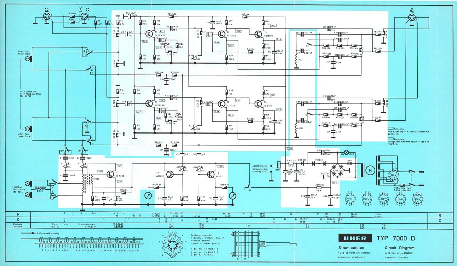
Uher 7000 D Schematic

This is the 2 pages manual for Uher 7000 D Schematic.
Read or download the pdf for free. If you want to contribute, please mail your pdfs to info@audioservicemanuals.com.

Page: 1 / 2
left right
Uher 7000 D Schematic

Extracted text from Uher 7000 D Schematic (Ocr-read)


Page 2

Teéhnische Deten:

Spartans:

Bandgescliwlnd lgkoiten:
(«medialiban

Mu; Spulangnrfla:

F raquenwmleng:
[DIN 4551i]

Fremdepsniiurigu lute nil:
tans cma's

Gleldtl Iutebwniahurig;
bel lacs c ms

Nadibarfianeldllmptiing:

Elngange-mnfindlichkeit;

Magfingc:

Inlr. ml inn ale Vi Ear spur

9.53 caia's; 19.05 eras

18 on Ovid-mews-

ilO-HODD l I: [ 9.53 en's].
40 IBM H2 [19.05 omit] '

so db
0.2 "/0 cgchanimua}

50 db

Mikrci: 350 VIZ: k0l'm
Radio: 4.5 irVr"? thm
Phone; 50 mVi2.2 mO'wm

0.75 Jr'l 5 ltOhm

Technical Specifications:

Recording Sense: 4 trad-es to

[ma 'riatlonul standard
Tape Speede: 3 34 5p;

7' 1 2 'a 5
Real Size: up ta 7
Frequency Fla: ponee: 40-ll-DOG cps at 3 3/4 ipe
(DINdSfili) 40-lS.DOD-:paat?l"2lpa

50 db at T 132 in:

0.2% at 7 If? ipa
{audible Iraqi-ermine nn'y]

Signdto-Noleo Hafle:
Wow snd Flutter:

.CI'III riiil Separation: 50 db
Inpul Senoitirity: Micro: 350 micro-volts at
2.3 kchms
Radio: 4.5 mil ivoltii at
4? kohrns

Phone; 50 m llivolte at
2.2 mugohms

Outputs: 0.15 vn'lta at 15 kofrra
Ivvnuaslgw;
"#92th war
-_ li-m u-r-- - - W-raevczcr- -... - . dun-n53: $.51 aw)

if: - Gen «II - -- - P'Ilfiflfl - m- heron-1r... ivl A» a)
li) II)
I. .t
M if
u ..'

r: i: i.
M :0
l a
.' I
a .'
z y
9 0
- 2 2
~ r r
-i - 5
5 9." at: 44 61 m I J ¥ 3 I i K-NL I

_ Sou ah-a -. w ~. wine-(gear -.-. -.~'nwr :5. ml;

4 a.» M --- - Pww - - ----=«')rwla 3?? 'N 9
_ an m
in _ ..- --- u
i: 'J
I [I
I: .3
I9 :0
I I
.t i
f s
z I
0 J
- 2 2
_ a _
- 5 - 6
_ , _ r
N! I"!

R as lereinstell u ng

Vor EInatellung IIIE' Hegler prOferi. ob Folgenda Spanrungen in der sneegebaneri Haho vorhanden sind:
an C 34 Iiogon 17V 4
an C 23 Iicgcn 35V

nae Autnamompfindlichlioit: Tangenerator an die Kontaltte 1 und «1 [pa'ellelxhalww u-yd 2 {Mame}
der Buchse .nadici" enschliefion und (a. 5 ml! boi lOCOl-lz e nspaisan. Beiriiebsarlemdiélter fluf
.Szareo' und Germ sluf .Aufnai'im' sclialten. fiegler .Pegal' volt s-ch'rehen.

Fahreiwoltmetar an die Kontakta l und 2 {Mseee} der Bud'sa é ensdilieflen. Auegengespanrrung dee
Tangeneraturc so einetellen. dae daa Ro-renvoitmeter 4 V amoigt. Hot-ammo tine-er jatzt an d e Kon-
mile 4 Md 9 (med-Italian and mi: H99 elmnhlls 4V ninsiellen.

Vor tinatellung dcr Aussteuerungaanzaige mulfi unbedingl die Aufnah-Mempfindlidikeit aural: warden.

Fl 30 Auaemucmngoennige [Kauai I): Tongenerator an die Kontakiel urid 2(Maese} der Duchse .Hndio
an:c".liafien unrl ca. SmV bai mt-ll elmspeisnn Belriebartersehaiter auf .Ste'ao' und Germ euf
.fiufnahrne" whiten. Healer .Pagei voli aufcrchen. Rahmoimeter an die Kontekla l and 2 der
EUChsc g, flthlieflen. Ausgnngsspenwng dcs Tongcnorstois an einstellaii. def} c'es ROhvHVOIUFIUWr
4V anZeIgt. Finale.- H 30 so «installon. den der Zoigor deg Anzcigeincimmanm :wischcn dem rotcn
um} c'em echwaraan Fold be»; an? 0 db staht.

RIM Auscleuerungeameige (Kauai ll): McBanordnung wie unter Aueateucrungsaaelge {Kannl I] be-
achriaben. Ea wlr-:l fiber dle Kamek'ie 4 Jnd 2 dar BL-dtse "Radio" uiiiucspoist urid fiber dis Konzukte t
und 2 dar Buchso g gemaaien Die Eiriatzelli. rig erfolgt mt Flcglcr R 34.

R 23 Wiederanheempfhdlchltailz Tongeneralor ar' :1 e Kontakoe 1 und 4 [para leladtaltien) und 2 [\Iaaaej
dar Buchse .Fiadio enamlienen urd so. 20 1W bei 1000i 2 einspalean, Batrlabaertananhaltar aLf
,Bluwo rind Geifil auf .Aulnahm' Rdtallier'. Hhhinnvollznater an dle Kortam 4 und 2 der Buehse é,
anschliccen. UHER-Teetba'td aullegcn me 000 Hzmit Vollauaatenrurg aufnehmen. Tonband zuriiw-
smile-i iind wiedergehnn Die an Hfihrnnvnltmekr angemigle Spani'rung ebleaen.

Réhrenvoltmator an die Kontakta l urid 2 def Buchae é anarhlielkn. Tc nhnnd 7un'lckspulon und wiader-
geben. lllt darn Ragler 823 die zuvor am ibhrerwolzrnetar angeeoigte Spannung einstellen.

Die HF-Vormagnellslarung beelnflum den Frequerizigsrg des corn 1.9. Di. unzen angage'aane Spannung
is! arn Mittelwart. die andgultlga E nsnallurig erfo gt nsc'n dcr Kanlmllo des Frequanzgaggee.

a I HF-Voriii-gnetislerung {Kaofl I): Gore: aut .Steroo urd .Aufnshme schalten.

Halirsnvoltrw'ier an Putk: A {a'ehe Abb.1] urid \ilasae madmllofion. MI: E 1 wire an Rfihrenvolcrnetar
cinc Scannurg iron ca. 25 V aingaetcllt '

R4 HF-Vorniagnelirlarung (Renal Ill: Hahremolimotei an Punki: H (sieha Abb. 1] anxh'IeBen. Mn: 34
«in! em Rbhrerwolcrnetar aim! Spannutg vnn ca. 75V eingeszalit .

' Mauung der swraaannunsz Die trmittlung z B. das meflwennungwbstandes nach CIN 454m] satzl

die Amneung von Mefigerajen ml! spa: e Ian Elgansntiefion voiavic. Da ceronige klefigerata m den
nelsten Werkatttmn nicht vorhandon si'vd mird die nachfolgcnd besrhriuaeno Mossung amptatiien:
NF-Millivnltmetyer en die Ko-mkaa 5 WM 2 hzw. 5 out! 2 tier Funds-5 "Radio/Phat. ansdflieflsn. UHEH-
Tastbend su. darn Gersi. volletsndig Iosalien (Hegla' -Pegel mat} auf Nul gcdmht warden] und im-
schéiefiend wiedergaben. Din dabal vem NF-Mlllvcltrnatar angemigto Span nu n5 dart max. [3 mV betrege n.

h._.

a..._._ .

Adjustment at Variable Resistors

P'n' to any adjustment of a variable to :isror chock whether the lollowrng voltage; are property e;-plied

ac nos: the respective caravan: n3;
across 3 34
across 8 23

1 7 v0 lta
35 v0 ts

329. Recording Sensitivity; dege the cit-meets 1 and 4 of the "Radio" aodler connect an and o
ne:illslor It; the bridged contacts 1 Md 4 and to contact 2 (ground) Bvd ead s eignal pr 1,000 up: at
approx. 51W. Sct no mode selector to 'Suaren' and set the recorder for racordlng cacraiicn Tum
Ilia "lmml cunlml fully chidtwiea. Connect 9. WM acroaa Iha contacts 1 am! 2 (ground) of the
town :5.

AcJu st the output volage of the audio oscllntor for e WM reedlrg of 4 value. Then connect the mM
across Jia contacts 4 and 2 and adjust an identical WW reading ol 4 volts by means cf R23.

H30, Receding Level Indication {Channel I): Connect an audio oscillator earner, the comma I and 2
{ground} of tho "Radio" socket and feed a signal of 1.01] cps at approx. 5 mV. Sgt the mode selector
to 'Srereo' and so: mo recorder tor resending operation. Turn the Lavel control lully clocloxlse,
Connect a VTVM across the contacts 1 and 2 of the code: 1%. Acluat the output writing: of the audio
uscillelor {or e W reading 0 4 vol».

Adjust Fl 30 so that the- pomter of :ha ramrdi-g !avr:| meter stands between the red and black bands
cf the scale. Le. the meter reads zero db.

RSI, Recording Level {Channel It]: Establish a measuring circuit as described for channel I in the
preceding paragraph. The sigma. is fed across the contacts 4 and 2 o. the Badio socket and is
measured: ac-uss 'he cmtncis 4 and 2 of the snake! 4,.

The adustment ls made by means at lhe~varieblc resistor ll 34.

H 33. Playback Sensitiviu: Bridge contacts I and 4 o. the 'Radio' sockci. connect an audio cwi IatO'
to the bridue contacts I and 4 and to contact 2 (ground) and feed a signvl 05' 1.0M cps el approx. 20 n'iV.
Set the mode selector la 'Ste'ea' and the recorder for record ng operation.

Cannact s WVM acres: the cement: 4 end 2 of the aod signal at 1.0% cu: at full level. Rewind memo: and play back the recorded signal. Read the 0mm
voltage indicated on the VIVM.

Connect a WVM semen the. connects 1 and 2 of the socket .g. Rewind the up; and play back the
recorded signal. Adest, by mas he of the vaneble resistor Fl 23. the ourth voltage ptwioufly indlcsted
on the VTVM.

The FlF-blaa influences the frenuenn' response of iiie -ecorc'er. 71¢ valtage mentioned balaw is a rresn
value. Final actusunent w'll be made atter the frequency rosporro has been checked.

H 1. RF-Bile (Chennai I]: Stat Ilia 'crwm'cr for slat-w recording operation. Connect a VTVM stress
point A (see fig. 1} and graund and adjust a VWM reading of approx 25! by means at R I.

B 4, fiF-Blaa (Uterine! fl]: Cannect a With! across point B (see fig. I} and ground and adjust a W
residing at app-Oat. 25 V by niee n3 of R 4.

Meeeurlrig tho Noin (unweighted). Connect an audio-fraucmy mill.voltmatcr across the contacts 3
and 2 MS and 7 manectiwely 0" the. "nadio scdtet Thread a UHF Test Tape and areee [I completely
{turn the recording Ieve' COHIOI fully ccunuorciodswiso]. fiew'nc' and pray back the tape. The noise
when indented on the die-frequency rnillivoltmater must not exceed 6 mil ivalta.