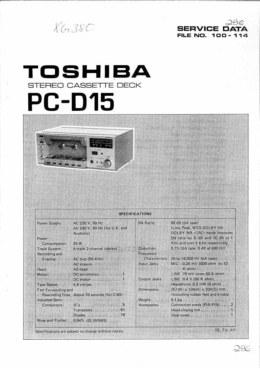
This is the 31 pages manual for Toshiba PC D15 Service Manual.
Read or download the pdf for free.
If you want to contribute, please mail your pdfs to info@audioservicemanuals.com.
PC-D15 l
CONTENTS
1. FEATUER ...................................................................... 2
2. OPERATING CONTROLS ........................................................ 3to4
3. OPERATING INSTRUCTIONS ..................................................... 5 106
4. TECNICAL POINTS ................ _ ............................................ 6 to 9
5. DISASSEMBLY INSTRUCTIONS ................................................. 10 to 12
6. BLOCK DIAGRAM ............................................................... 13
7. ELECTRICAL ADJUSTMENT ................................................... 13 to 17
TEST EQUIPMENTS ........................................................ 13 to 14
RECORD/PLAYBACK HEAD AZIMUTH ADJUSTMENT ..................................... 14
PLAYBACK SENSITIVITY ADJUSTMENT ............................................... 15
BIAS LEAK ADJUSTMENT ........................................... . ............. 15
LINE INPUT SENSITIVITY ADJUSTMENTS ............................................. 15
LEVEL METER ADJUSTMENT ...................................................... 16
RECORD/PLAYBACK FREQUENCY CHARACTERISTIC ADJUSTMENT ......................... 17
RECORD/PLAYBACK SENSITIVITY ADJUSTMENT ....................................... 17
8. P.C. BOARD PARTS LOCATIONS ..................................................... 18
9. SCHEMATIC DIAGRAM (MAIN) ..................................................... 19
SCHEMATIC DIAGRAM (METER DRIVE & LED BLOCK) .................................... 20
SCHEMATIC DIAGRAM (POWER SUPPLY BLOCK) ........................................ 20
SCHEMATIC DIAGRAM (LOGIC BLOCK) ............................................... 20
IO. WIRING ...................................................................... 21
11. CABINET PARTS LOCATIONS ...................................................... 22
12. MECHANICAL PARTS LOCATIONS ................................................... 23
13. PARTS LIST ............................................................... 24 to 29
0 Two motors and IC logic control.
1. FEATURES
0 Many functions in a compact housing, such as a
Feather-touch operating buttons.
Direct button change without using the STOP bUtton
protects the tape.
0 Bar-graph peak meters with LEDs.
Electronically controlled bar-graph peak meters are
more responsive, accurate, and easier to read than
mechanical meters.
Levels below 0 dB are displayed in green and levels
above 0 dB in red.
0 Automatic tape selector detects the chrome tape
detection hole and automatically switches the mode
from NORMAL to CHROME, and vice-˜versa.
Pushing the Fe-Cr switch enables automatic FER RO-
CHROME and CH ROME mode selection.
memory counter, automatic play, unattended record-
ing, and alarm playback.
An all sendust (AS) head with new sendust laminated
core assures lowdistortion widerange recording.
Attractive all-aluminium housing, including the rear
panel.
Direct loading allows easy and secure tape loading
and unloading with a good view of the tape.
Dolby-œ system.
Remote control jack.
Noise Reduction System is manufactured under
license from Dolby Laboratries Inc. "Dolby" and
the doublevD symbol are trademarks of Dolby Labo-
ratries Inc.
l PC-D15 PC-D15
BACK VIEW
[MIC]
i-Microphone Jacks
Connect a microphone (Optional) to these jacks;
right channel.
[OUTPUT]
Output Control
Turn this control to adjust the [LlNE OUT] jack level
to the tuner and record player levels. This control does
not affect the headphone levels.
LINE IN]
Line Input Jacks
External signals are input to these jacks throngh pin
cords:
right channel.
LINE OUT]
Line Output Jacks
The cassette deck signals are output from these jacks:
channeL
[REMOTE]
Remote Control Jack
Connect the remote controller (Option RM~15l to this
jack.
Note: The rating and serial number plate is on the
bottom of the set.
Figure 2
-4;
3. OPERATING INSTRUCTIONS
Notes:
I Operating buttons are not effective for 3 seconds
after the power is turned ON.
0 All operating buttons are reset when power is cut
OFF.
PLAYBACK
1. Load tape
button
3. Push the [ > ] (Plavl
Figure 34
0 Push the [Fe-Cr] button when using ferrochrome
T399.
0 If the [ II ] (Pause) button is pushed, the [ b ](Plav)
button is not effective.
0 All operating buttons are ineffective until a tape is
loaded. If a tape is unloaded during fast forward (FF)
or rewind (REW) operation, the operating buttons
are reset.
2. Push the [DOLBY NR]
button to play back a
Dolby-recorded ta pet
0 The full automatic stop mechanism (Full ASO) stops
recording, playback, fast forwarding, or rewinding
when the tape end is sensed.
I RECORDING FROM RECORD PLAYER OR RADIO
From amplifier
up
(Tuner or Phone)
3. First, push the [ II ]
(Pause button).then push
the [ I ](chordi and
[ p ] (Playlbuttons si-
multaneously to adjust
the recording levels by
reading the digital me-
ters.
1. Load tape with erase-
prevention tab.
4. Push the [ ll ] (Pause)
button again.
2. Push the [DOLBY NR]
button for recording "n
the Dolby system.
Figure 4.
0 Push the [Fe-Cr] button when using ferrochrome
tape.
0 Adjust recording levels so that the red LEDs flicker
in red (about 0 through +3 dB].
I RECORDING WITH MICROPHONE
Insert the microphone plugs into the microphone jacks
[MIC] on the rear panel and perform the above proce-
dure.
o The microphone jacks have priority to the [LINE
IN] jacks if pin cords are connected to the [LINE IN]
jacks.