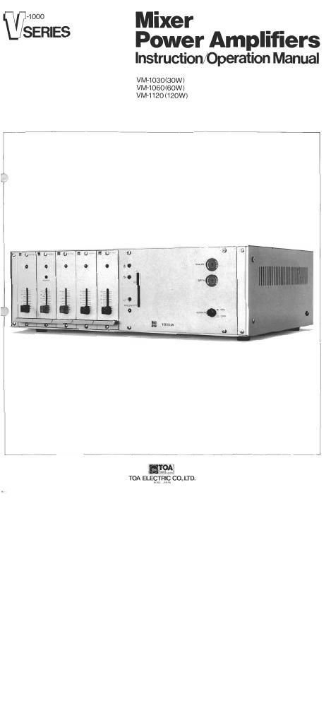
Toa vm 1030 1060 1120 owners manual

This is the 107 pages manual for toa vm 1030 1060 1120 owners manual.
Read or download the pdf for free. If you want to contribute, please mail your pdfs to info@audioservicemanuals.com.

Page: 1 / 107
left right
toa vm 1030 1060 1120 owners manual

Extracted text from toa vm 1030 1060 1120 owners manual (Ocr-read)


Page 2

. Mixer Power Amplifier Index ' ,

General Description .......................................... 2
Features .................................................... 3
Specifications ................................................ 4
Appearance ............................................... 4
Installation
Using Rack Mounting Brackets And Stacking Brackets ......... 5
Speaker Terminals ......................................... 6
3-Wire/4-Wire System Wiring ............................... 6
DC Power Connection ...................................... 7
Line Outputs .............................................. 7
Program Input ............................................. 8
Specifications Of Input Modules And Equipment
Blank Panels V-1001, V-1002 ................................ 9
Chime Signal Module V-1015 ........................... 10~13
Microphone Preamplifier Modules
V-lOSI/V-1151/V-1251/V-1052 ........................ 14~29
Phono Preamplifier Module V-1053
AUXI Preamplifier Modules V-1054/V-1154 ............ 30~38
Program Selector Module V-1061 ....................... 39~42
Paging Microphone VR-1001 ............................... 43
Remote Microphone (6 ch) VR-1006 ..................... 44~50
Mounting Brackets YM-003. Stacking Brackets
YMvOB, YM-OQ, YM-IZ .................................. 51
Connecting Cables YR-1005, YR-1010, YR-IOZO ............... 52
How To Make Adjustments
Adjusting Mute Level Of AUX Input ........................ 53
Adjusting Output Level .................................... 53
Adjusting Tone Control .................................... 53
Assembling And Adjusting Fault Detection Circuit .......... 54~55
Troubleshooting
Parts List ............................................ 55~60
Flow Chart For Checking .................................. 61
Block Diagrams ........................................... 61
Typical Solid-State Component Configuration ................ 62
Schematic Diagrams ................................... 63~66

,1,