Toa n 8031ms

This is the 4 pages manual for toa n 8031ms.
Read or download the pdf for free. If you want to contribute, please mail your pdfs to info@audioservicemanuals.com.

Page: 1 / 4
left right
toa n 8031ms

Extracted text from toa n 8031ms (Ocr-read)


Page 1

fl TOA

INSTALLATION MANUAL

FLUSH-MOUNT HANDS-FREE

MASTER STATION

N-8031 MS

Thank you for purchasing TOA's Flush-Mount Master Station.
Please carefully follow the instructions in this manual to ensure long. trouble-free use of your equipment.

1. GENERAL DESCRIPTION

The N-8031MS is a flush- or surface-mount master station
designed to operate in conjunction with TOA IP Intercom
Exchange and features high quality hands-free
conversation.

Connecting a foot switch or other external switch to the
external dial input terminal permits one-touch dialing
operation by way of such switches.

Handset conversation can be made in conjunction with the
optional PIS-191.

2. WALL MOUNTING

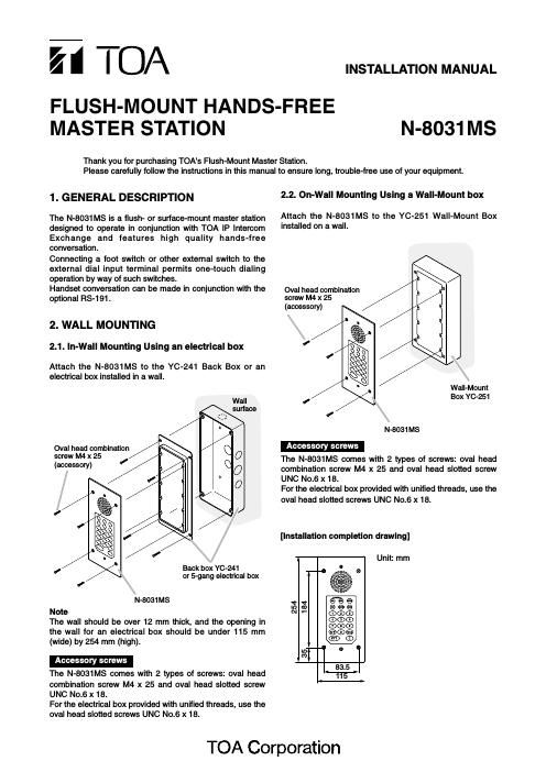
2.1. ln-Wall Mounting Using an electrical box

Attach the N-8031MS to the YC-241 Back Box or an
electrical box installed in a wall.

Wall
surface


Oval head combination
screw M4 x 25
(accessory)

Back box YC-241
or 5-gang electrical box

N-8031MS
Note
The wall should be over 12 mm thick, and the opening in
the wall for an electrical box should be under 115 mm
(wide) by 254 mm (high).

Accessory screws

The N-8031MS comes with 2 types of screws: oval head
combination screw M4 x 25 and oval head slotted screw
UNC No.6 x 18.

For the electrical box provided with unified threads, use the
oval head slotted screws UNC No.6 x 18.

2.2. On-Wall Mounting Using a Wall-Mount box

Attach the N-8031MS to the YC-251 Wall-Mount Box
installed on a wall.

Oval head combination
screw M4 x 25
(accessory)

Wall-Mount
Box YC-251

N-8031 MS

Accessory screws

The N-8031MS comes with 2 types of screws: oval head
combination screw M4 x 25 and oval head slotted screw
UNC No.6 x 18.

For the electrical box provided with unified threads, use the
oval head slotted screws UNC No.6 x 18.

[Installation completion drawing]

Unit: mm

254
184

35

TOA Corporation

Page 2

3. WIRING

3.1. Connection to the Exchange

N-8000EX Exchange
T 16 lines T

Mini-clamp connector
(Supplied with the N-SOOOEX)

E-7000TB
Terminal board
3 F
0 Both upper and lower
terminals (clip terminals)
are internally connected.
0
3

Twisted pair cable

63
6E

Removable terminal plug (2P)
(accessory)

Line connection terminals

N-8031 MS rear

To connect the cables from the N-8000EX Exchange to the
N-8031MS, use the removable terminal plug (2P) supplied
with the N-8031MS.

The cables have no polarity.

3.2. Connection to RS-191

Connecting the RS-191 Option Handset to the N-8031MS
permits handset conversation.

Step 1. Remove the handset jumper attached to the N-
8031MS's handset connection terminal, then
insert it to the socket on the RS-191's rear PC
board.

RS-191 rear

N-8031MS rear


Socket
_ % _.| = .7

Handset connection terminal

Handset jumper

Note
Though the socket on the PC board is faced inside, you
can insert the handset jumper into the socket from the
side.

Step 2. Install the ferrite clamp (supplied with the N-
8031MS) onto the RS-191's handset cables.
Then, connect the cables to the N-8031MS's

handset connection terminal.

Ferrite clamp (accessory)

Note
Run the cables along the ferrite
groove, and clamp them.

~~_ _.

Handset cable
Handset cable

fig.

Handset connection terminal

3 man
finance:

N-8031 MS