Toa ax 1000

This is the 5 pages manual for toa ax 1000.
Read or download the pdf for free. If you want to contribute, please mail your pdfs to info@audioservicemanuals.com.

Page: 1 / 5
left right
toa ax 1000

Extracted text from toa ax 1000 (Ocr-read)


Page 1

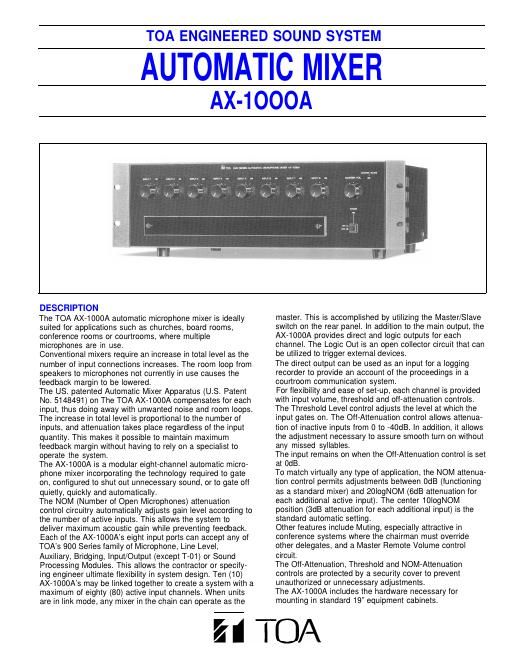
Front View Input Volume ControlMaster Volume Control Channel Controls: Gate-On LED Master/Slave LED THR OFF ATTNOM ATTPower Switch and LED Variable ThresholdEach threshold control adjusts its channels detector, raising and lowering the baseline sensitivity to an incoming signal. It determines how easily the input will gate on. Threshold is independent of the Off-Attenuation setting. Variable Off-Attenuation This control, permitting continuous adjustment of a channels Off-Attenuation (depth), operates from 0dB (full CW) to -40dB (full CCW). In the 0dB position, the channel acts as a conventional mixer input. At that setting there is no attenuation of the input whether it is above or below threshold. Channel output: Relation of Threshold and Off-AttenuationControls (simplified): Channel System Output Gain: Adjustable NOM Attenuation Automatic gain reduction is continuously variable from none to 20logNOMdB. (NOM=Number of Open Mics.) At the center detent, the attenuation of system output gain follows the standard formula 10logNOM. When the control is moved clockwise, the attenuation is deeper, moving from 10logNOM to 12logNOM, 15logNOM, etc. Attenuation is at a maximum fully clockwise, following the formula 20logNOM. With the control set fully counterclockwise there is no system output gain attenua- tion and the AX-1000A functions as a normal mic/line mixer. Between no attenua- tion and the detent, output gain is attenuated more and more up to 10logNOM. 20logNOM 20logNOM 2 4 Active Inputs (NOM) 8Inputs 0 dB Attn. 10 16 20 40 80Inputs

Page 2

Rear View Remote Master Volume Terminals Logic Output Terminals Module Direct-Output Jacks (1/4) System Mute Terminals(Priority Override) Channel Mute DIP Switches Modular Inputs In a significant advance for automatic mixing systems, the AX-1000A uses TOAs standard 900 Series input modules. Any combination of Mic and Auxiliary Preamps can be specified in an installation. If it is important to allow for future expansion, only a few of the input ports need be used. Logic outputs, direct outputs, link in and out, system mute terminals and remote master volume control terminals are located on the rear panel. Function Select Link In& Out Master/ Slave Switch SLAVE Main Output Terminal 600 ohms or 150 ohms System Mute (Priority Override) A DIP switch determines which channels are muted when the two rear-panel mute terminals are shorted by a relay or switch closure. AX-1000A Internal Muting occurs within the mixer, after the signal has left the input module itself. Thus, any 900 Series input module will be muted when the contacts are closed. The module does not have to be a 900 Series muting module,. In fact, by using 900 Series muting modules, two levels of muting are possible. The first level can be automated. It utilizes the Mute Send and Mute Receive features of certain 900 Modules. The second level utilizes the Mute built into the AX-1000A. Direct Outputs Each channels Direct Output provides a signal from the corresponding module. It has been processed by the preamplifier and other circuitry in the module itself, including, for example, compression in the case of the U-61 module. However, the Direct Output signal is unaffected by the action of the AX-1000As gating, muting, or gain-sharing circuits. Logic Outputs Each channels Logic Output is an open-collector circuit. The logic outputs may be connected to relays for automatic initiation of events in an automatic zonal switching system, triggering video camera controls, etc. Link In and Out When AX-1000A mixers are run in multiple, one of the mixers operates as the Master and the rest operate as Slaves. The Master/Slave relationship is determined by the rear-panel slide switch. The Master is connected to the Slaves using the Link In and Out connectors. An optional Link cable is available. Main Output The Main Output barrier strip can be configured for 150 ohms or 600 ohms operation by moving the jumpers (provided).