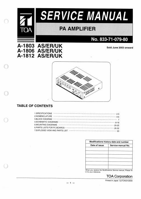
Toa a 1803 1806 1812 part 1

This is the 13 pages manual for toa a 1803 1806 1812 part 1.
Read or download the pdf for free. If you want to contribute, please mail your pdfs to info@audioservicemanuals.com.

Page: 1 / 13
left right
toa a 1803 1806 1812 part 1

Extracted text from toa a 1803 1806 1812 part 1 (Ocr-read)


Page 1

SER VICEMANUA a

TOA

A-1803 ASIER/UK
A-1806 ASIER/UK
A-1812 ASIER/UK

Sold June 2003 onward

TABLE OF CONTENTS
1-SPECIFICATIONS ............................................ 2_3
2,NOMENCLATURE ................. 4.5
3.BLOCK DIAGRAM -------------------- 7
4.SCHEMATIC DIAGRAMS ------------------- 849
5.MOUNT|NG DIAGRAMS ---------------- 2025
6.PARTS LISTS FOR PC BOARDS ............. 26,32
7.EXPLODED VIEW AND PARTS LIST ........................................... 33

Modificafions history date and number

Date of issue Service manual No.

When you recelve the Modmcalions Service manual. Please ml
in {or your reference.

TOA Corporation

Printed in Japan GJTOA0312658

Page 2

MODEL A-1 800 SERIES

1. SPECIFICATIONS

Model No. A-1803 I A-1806 I A-1812
Power Source 220 - 230 V AC or 240 V AC, 50/60 Hz

24 V DC (M4 screw terminal)
Rated Output 30 W 60 W 120 W

Power/Current Consumption

AC operation:
80 W (rated output),
37 W (EN60065)
24 V DC operation:
2.0 A (rated output),
1.0 A (EN60065)

AC operation:
158 W (rated output),
66 W (EN60065)

24 V DC operation:
3.8 A (rated output),
1.6 A (EN60065)

AC operation:
260 W (rated output),
110 W (EN60065)
24 V DC operation:
7.0 A (rated output),
2.8 A (EN60065)

Frequency Response

50 - 20,000 H2 (#3 dB)

Distortion Under 2% at 1 kHz, rated power
Input MIC 1: -60 dB, 600 Q, electronically-balanced, combined type of
XLR»3-31 equivalent and phone jack, DIN socket (5 pins)
MIC 2 -- 3: -60 dBZ, 600 Q, electronically-balanced, combined type of
XLR-3-31 equivalent and phone jack
AUX 1 (MOH): -20 dB, 10 k0, unbalanced, RCA pin jack
AUX 2: -20 dB, 10 k0, unbalanced, RCA pin jack
AUX 3: -20 dB, 10 k9, unbalanced, combined type of XLR-3-31
and phone jack
TEL: -20 dB'Z, 10 k0, electronically-balanced, M3 screw
terminal1
EMERGENCY: 0 dB, 600 Q, unbalanced, M3 screw terminal"
Output REC: 0 dB, 600 Q, unbalanced, RCA pin jack
LINE 1, 2: 0 dB, 600 Q, unbalanced, RCA pin jack
MOH: 0 dB, 600 Q, transformer balanced, M3 screw

terminal

SPEAKER SELECTOR: 2 zone, high impedance5 (100 V line), individual
selector switch, M4 screw terminal1

DIRECT SPEAKER OUT: High impedance5 (100 V line), M4 screw terminal,
Low impedance (4 - 16 9), M4 screw terminal

Note: Both Low and High impedance terminals cannot be used at the same time.

Phantom Power

ON or OFF for each MIC 1 - 3 with switch setting

S/N Ratio
(Band Pass: 20 - 20,000 Hz)

Over 100 dB (Master volume: min)
Over 76 dB (Mastervolume: max)
Over 60 dB (MIC 1 - MIC 3)
Over 76 dB (AUX 1 - AUX 3)
Over 90 dB (TEL)

Over 96 dB (EMERGENCY)

Tone Control

Bass: :10 dB at 100 Hz, Treble: 110 dB at 10 kHz

Control Input

TEL: No-voltage make contact input

Open voltage: 24 V DC

Short-circuit: under 5 mA, M3 screw terminal
EMERGENCYG: No-voltage make contact input

Open voltage: 24 V DC

Short-circuit: under 10 mA, M3 screw terminal1

Control Output

Power remote: Open collector output
Withstand voltage: 35 V DC
Control current: under 50 mA, M3 screw terminal

Chime Hone, 2-tone, or ascending 4-tone chime, or None selectable with switch
setting, activated at MIC 1's DIN or CONTROL TEL terminal.
Indicator 5-point LED output level meter, Power indicator LED, Zone indicator LEDs,

Emergency LED, TEL LED

_2_