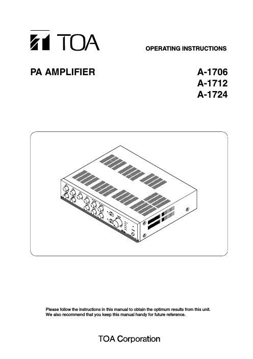
Toa a 1700 manual

This is the 10 pages manual for toa a 1700 manual.
Read or download the pdf for free. If you want to contribute, please mail your pdfs to info@audioservicemanuals.com.

Page: 1 / 10
left right
toa a 1700 manual

Extracted text from toa a 1700 manual (Ocr-read)


Page 1

OPERATING INSTRUCTIONS


71.

A-1706
A-1712
A-1724

PA AMPLIFIER

Please follow the instructions in this manual to obtain the optimum results from this unit.

We also recommend that you keep this manual handy for future reference.

TOA Corporation

Page 1

OPERATING INSTRUCTIONS


71.

A-1706
A-1712
A-1724

PA AMPLIFIER

Please follow the instructions in this manual to obtain the optimum results from this unit.

We also recommend that you keep this manual handy for future reference.

TOA Corporation

Page 1

OPERATING INSTRUCTIONS


71.

A-1706
A-1712
A-1724

PA AMPLIFIER

Please follow the instructions in this manual to obtain the optimum results from this unit.

We also recommend that you keep this manual handy for future reference.

TOA Corporation

Page 2

TABLE OF CONTENTS

1. SAFETY PRECAUTIONS ................................................................................ 3
2. GENERAL DESCRIPTION ............................................................................. 4
3. FEATURES .......................................................................................................... 4
4. NOMENCLATURE AND FUNCTIONS
Front ......................................................................................................................... 5
Rear .......................................................................................................................... 6
5. CONNECTIONS
5.1. Speaker Connections ........................................................................................ 7
5.2. Remote Volume Control Connection ................................................................. 7
5.3. Remote Power ON/OFF Control Connection .................................................... 7
5.4. External Equipment Connection
to the LINE OUT and PWR AMP IN Terminals ................................................. 8
6. FUNCTION SWITCH SETTINGS ................................................................. 8
7. SPEAKER ZONE SELECTION ..................................................................... 8
8. INSTALLATION .................................................................................................. 8
9. RACK MOUNTING ............................................................................................ 9
10. CONTROL SETTINGS ..................................................................................... 9
11. BLOCK DIAGRAM ........................................................................................... 10
12. SPECIFICATIONS ............................................................................................ 11
Accessories .............. 11
Optional products .................................................................................................... 11

13.

DIMENSIONAL DIAGRAM ............................................................................ 12