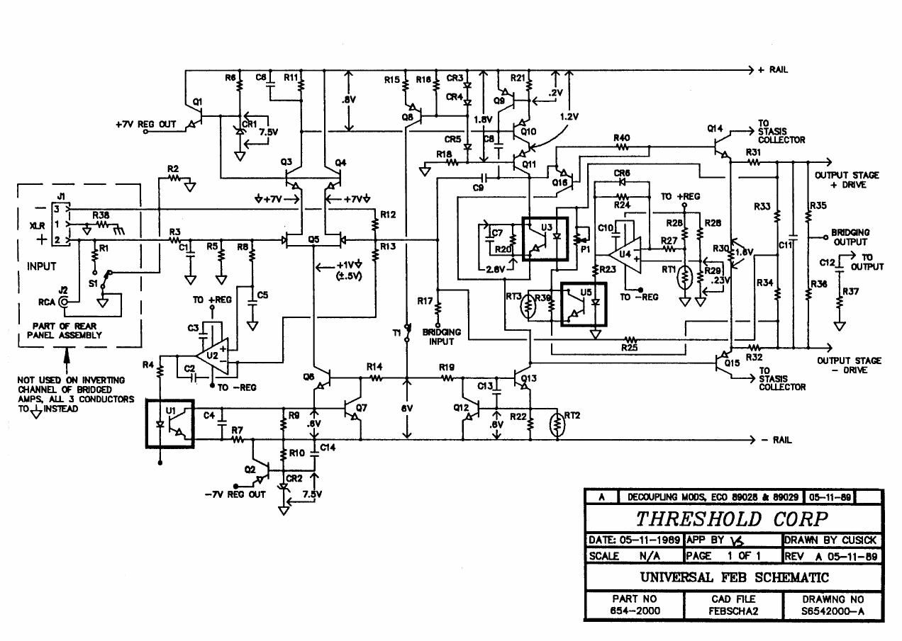
Threshold s series schematics

This is the 3 pages manual for threshold s series schematics.
Read or download the pdf for free. If you want to contribute, please mail your pdfs to info@audioservicemanuals.com.

Page: 1 / 3
left right
threshold s series schematics

Extracted text from threshold s series schematics (Ocr-read)


Page 2

R1 R2 AD3 R5 R7
600 22K 7 . 6v 2 _ 2K 150
915
0'5 I as HPSU1D
2N4250 c1 2N4250
RS _ R19
_ Q7 47
MPSA92
7 R as
D1 22K MPSA92
93 a4 7.6V
1 D- I/ |mom
2 3- n l\ PSAez 08 -<:
3 3- MPSA42
4 HPSA1e -----C
______________-__{
g 01 02 :
7 ;)__-| 2N5566 ____.._-c
3
9 -c
10 |
011 \1 R10 1 R 014
MPSA42 RIB
KI R12 4-7" 4'75 R15 N "P5942 R16 47
475 475 100
D2 916
7.6V MPSUSO
R11 012 013 R14
301 NPSA42 MPSA42 150
I
INPUT HEADER: OUTPUT HEADER:
PIN 1 COMPENSATION PIN 1 UNREGULATED + SUPPLY
PIN 2 cascoDE ADJUST PIN 2 REGULATED + SUPPLY
PIN 3 ZENER FILTER / ADJUST PIN 3 + COMPENSATION
PIN 4 GROUND PIN 4 + DRIVE oUTPUT
PIN S ZENER FILTER / ADJUST PIN S BIAS POT
PIN 6 + INPUT PIN 6 BIAS POT
P N 7 - IN PIN 7 - DRIVE oUTP
I PUT UT THRESHOLD CORP
PIN e THERMAL SNIICH PIN a - COMPENSATION APPRoVED BY: Pass
PIN 9 ZENER FILTER / ADJUST PIN 9 REGULATED - SUPPLY DRRHN BY: P955
PIN 10 OFFSET ADJUST PIN 1o UNREGULATED - SUPPLY UNIVERSQL GM" MODULE

T-mawmuwun»

ocumsnt Number

EV
NC

Qpril 17. 1990FSEeet