Threshold phantom acoustics shadow brochure

This is the 18 pages manual for threshold phantom acoustics shadow brochure.
Read or download the pdf for free. If you want to contribute, please mail your pdfs to info@audioservicemanuals.com.

Page: 1 / 18
left right
threshold phantom acoustics shadow brochure

Extracted text from threshold phantom acoustics shadow brochure (Ocr-read)


Page 1

_ Acoustics: Active Low Frequency
Acoustic Control

The control of low
frequency room
resonances through the
application of active
suppression means

Author: Nelson Pass
May I 2. 1 988

An introduction from Phantom
Acoustics:

Although passive methods
for treating room condltions

are fem r, the Phantom
Acoustics Shadow active low
frequency trap is a new prod-
uct and technology insofar as
the audiophile community is
concerned.

Over a year ago Phantom
Acoustics realised that the
most efficacious solution to
room resonance problems
encountered by the home
music listener would have to
be addressed by an active
system.

To develop such a home
system Phantom Acouetlce
enlisted the consulting exper-
tise of a design team under
the direct supervi on of
Nelson Pass. phy cist and
acknowledged leader in inno-
vative electronic design.

The following is a white
paper of his authorship which
will enable the interested
audio enthusiast to appreciate
room resonance problems and
the solutions which may be
applied.

1 Background

We are striving to achieve the most
realistic audio reproduction possi-
ble. We want the sound impinging
on our ears to be a perfectly faithful
copy of that experienced at the
original event, and we are willing to
go to a lot of trouble to obtain that
performance. Every link in the chain
carries the full responsibility for the
integrity of the information, and we
scrutinize each component for
flawed handling of the sonic expe-
rience. The listening environment is
a major component in this chain
and is one of the worst offenders
against realism

Of all the varieties of distortion,
let's oonsiderjust the amplitude and
phase response. With modern

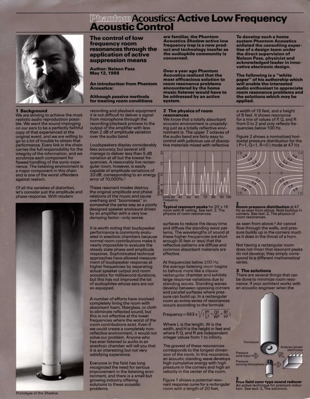
Prototype of the Shadow

recording and playback equipment
it is not difficult to deliver a signal
from microphone through the
recording/playback process to the
output of the amplifier with less
than 2 dB of amplitude variation
over the audio band.

Loudspeakers display considerably
less accuracy, but several still
manage to deliver less than 5 dB
variation at all but the lowest fre-
quencies. A reasonably live rectan-
gular room, however, is easily
capable of amplitude variations of
20 dB, corresponding to an energy
error of 10.000%.'

These resonant modes destroy

the original amplitude and phase
relations of the music and cause
overhang and "boominess" in
somewhat the same way as a poorly
designed speaker enclosure driven
by an amplifier with a very low
damping factor-only worse

It is worth noting that loudspeaker
performance is commonly evalu-
ated in anechoic chambers because
normal room contributions make it
nearly impossible to evaluate the
steady state phase and amplitude
response. Sophisticated technical
approaches have allowed measure-
ment of loudspeaker response at
higher frequencies by separating
actual speaker output and room
acoustics for millisecond durations,
but this has not improved the lot

of audiophiles whose ears are not
so equipped.

A number of efforts have involved
completely lining the room with
absorbent foam, fiberglass, or cloth
to eliminate reflected sound, but
this is not effective at the lower
frequencies where the worst of the
room contributions exist. Even if
we could create a completely non-
reflective environment. it would not
solve our problem. Anyone who
has ever listened to audio in an
anechoic chamber will tell you that
it is an interesting but not very
satisfying experience.

Everyone in the field has long
recognized the need for serious
improvement in the listening envi-
ronment. and there is a small but
growing industry offering
solutions to these acoustic
problems.

0
N

In

Declble mlansify

add

2 The physics of room
resonances

We know that a totally absorbent
acoustic environment is unsatisfy-
ing just as a totally reflective envi-
ronment is. The upper 7 octaves of
the audio band are fairly easy to
control with judicious use of absorp-
tive materials mixed with reflective

a width of 15 feet, and a height
of 8 feet. It shows resonance
for a mix of values of E Q. and R
from O to 2 and only reflects fre-
quencies below 100 Hz.

Figure 2 shows a normalized hori»
zontal pressure distribution for the
l P=1, 0:1. R=0 ) mode at 47 Hz

I

T ical resonant In for 20 x 15
rovoprn with 8 ceilinggge text: 2, The
physrcs of room resonances.

surfaces to reduce the decay time
and diffuse the standing wave pat-
terns. The wavelengths of sound at
these higher frequencies are short
enough (6 feet or less) that the
reflective patterns are diffuse and
common absorbent materials are
effective.

At frequencies below 200 Hz,

the average listening room begins
to behave more like a classic
rectangular chamber and exhibits
large response variations due to
standing waves. Standing waves
develop between opposing corners
and parallel surfaces where pres-
sure can build up. In a rectangular
room an entire series of resonances
occurs according to the formula:

2 2
Frequency=563 x ll ( L1 +%+%l

Where L is the length, W is the
width. and H is the height in feet and
where P. 0. and R are independent
integer values from 1 to infinity.

The gravest of these resonances
corresponds to the longest dimen-
sion of the room. In this resonance,
an acoustic standing wave develops
high cumulative energy with high
pressure in the corners and high air
velocity in the center of the room.

Figure 1 shows a potential reso-
nant response curve for a rectangular
room with a length of 20 feet,

1.00gs : 0910
0.6 h l o 0.3
o: ' «I
0'} l a»:
o __ __ ____
'- l
a q? i 01 a.
.n A--~-n-~------A-- a «1 v o: a
o "9 3 9 e
~19 . 0-
_fi_ _ 1.0 ; LO
20mm 40 50 60 70 30 90100
Frequency 2

Room pressure distributionat 47
Hz as seen from above. Note buildup In
corners. See text: 2, The physrcs of
room resonances.

as seen from above.2 Air cannot
flow through the walls, and pres-
sure builds up in the corners much
as it does in the throat of a horn.

Not having a rectangular room
does not mean that resonant peaks
do not develop; they simply corre-
spond to a different mathematical
series.

3 The solutions

There are several things that can
be done to minimize room reso-
nance. If your architect works with
an acoustic engineer when the

Transducer

AnslySIs [power
electronics
Pressure
zone Input

Pressure
sensing microphone gré) '

Free field zone type sound reducer
An active techni us for pressure reduc-
tion. See text: 3, he solutions.

Page 2

Sound pressure

Phantom Acoustics Active Low
Frequency Acoustic Control.

The control of low frequency room resonances
through the applicatlon of active suppression means.

Prlnled In USA

room is first designed, significant
improvements can be made in its
shape to help avoid the worst of
the resonant modes.

If you don't have that luxury you
can consider the use of mostly
ineffective absorptive surface treat-
ments. You can place very large
diffusing objects and shapes in the
room to break up the geometry of
standing waves. Or you can install
passive bass traps to help soak up
the unwanted energy}l

There is yet another possibility.
Observing that the room resonance
depends on high pressure buildup.
particularly in the corners, we can
conclude that it is possible to pull
the rug out from under resonance
by reducing the pressure in the
corners. One way to do this is with
the ever popular chain saw Simply
slice away the offending comer and
expose the room to the unbounded
environment outside. This does not
eliminate every possible mode of
resonance but will take much of the
wind out of them.

As a practical matter, though, it is
not desirable or necessary to carve
up the room. If we could postulate
a virtual sonic "black hole," a device
which creates an acoustic region
where the pressure is greatly
reduced, we could place it in the
corners and achieve roughly the
same result.

m 19.
-A-l-l-.-

i i ' i0

r 159

9 .
g l ,
5 l 1
'10»; 30 40 so so 100 200
Frequency

Sound pressure Induction for low
frequencies. See text: 3, The solutions.

The concept for such a device has
been around since at least 1953
when Olson and May described
what is referred to as a free field
zone type sound reducer? It con-
sisted of a simple circuit of micro-
phone, amplifier, and loudspeaker.
set in a loop so as to define an
acoustic region of low pressure.
They went on to describe mounting
such a device in the corners of a
room so as to maximize its effect
by presenting it with the large
acoustic load experienced there.

In one of the few cases where he
did not precede actual science. sci-
ence fiction author Arthur C. Clarke
humorously described such a device
in his 1954 short story "Silence
Please" wherein its hapless inven-
tor is killed by exploding capacitors
(which had absorbed the sound
energy) after the device had been
employed in a concert hall to
silence an opera performance)5

5

Pressure reduction zones (equivalent
to removal of room boundaries wrthin
zones) created by epair of .Phantorn
Acoustic Shadows "I a tyfzical 8 calling

room. See text: 3, The so utions.
Such a circuit is depicted in figure
3, where you can see the simplified
topology. A microphone is used to
sense the pressure in a particular
zone and sends its signal to an
amplifier which amplifies this sig-
nal and drives a transducer in such
a way so as to cancel the pressure
sensed by the microphone. The
loop that is created depends mostly
on the quality of the microphone.
as any distortion produced by the
amplifier and transducer are
reduced by the feedback of the
system.

Beyond the simplified schematic,
the electronics for an actual unit
must contain circuitry to compen-
sate for the amplitude and phase
response of the transducer so as to
assure loop stability, and a power
supply for a high quality condenser
microphone.

The/effect on a roughly spherical
zone around both transducers is
depicted in figure 4, where the
approximate pressure reduction is
shown over the range of bass fre~
quencies for a spherical volume 2
feet in diameter and 4 feet in
diameter

A working copy of this device was
under development in 1987 and
was demonstrated co~incidentally
with the Winter Consumer Elec-
tronics Show in Las Vegas. January,
1938. It is in current production by
Phantom Acoustics. The Shadow,
its consumer embodiment, consists
of two so- called "black hole" mod-

ules, one at each end of an inter-
nally damped 7 foot tube which
places them within 6 inches of the
3 sided surface intersection at the
corners of an average 8 foot ceiling
room. A pair of Shadows operate
so as to create four acoustic zones
of low pressure (figure 5) which
operate from below 20 Hz to
approximately 200 Hz. In so doing
they simulate openings to an out-
side unbounded area and break up
the high pressure corner patterns
which support room

resonance.

They can be placed effectively any-
where in a room, although they
are most effective in corners when
used with conventional loudspeak-
ers. Interestingly, they have a sig-
nificant benefit for bipolar types of
loudspeakers such as electrostatic
or other panels which radiate front
and back. Such loudspeakers

have an inherent problem in repro-
ducing low frequencies because
the rear wave is out of phase with
the front wave, and at low frequen-
cies the two reach around the sides
of the loudspeaker and cancel each
other. By placing a "black hole"
module behind a bipolar panel, you
can cancel much of the rear wave
and extend the perceived low fre-
quency performance of the panel
considerably.

The particular devices produced
by Phantom Acoustics are capable
of absorbing high sound pressure
levels. We can place a high effi-
ciency woofer (JBL LE-15Al within
the zone and drive it at full power
(160 Watts continuous sine wave)
without exceeding the capacity of
the circuit or observing transducer
distortion.

The Phantom Acoustics Shadow
active low frequency absorber is a
superior alternative to passive
techniques for suppressing the
pressure buildups that support res-
onance characteristics in the room.
When used with proper loud-
speaker/listener placement and the
moderate use of passive absorp«
tion in lesser pressure zones it can
greatly enhance the reality of the
listening experience. In an industry
that will expand large efforts for
small improvements, it is a very cost
effective approach.

References:
1 Knudsen, V.O., JASA, July 1932.

E. 20.

2 eranek, LL., Acoustics, 1954,
pp. 287-291.

3 Olson, US patent 2,502 020.
Bedell at all, us patent 1,160,638.
Olson, H.F. and Ma , JASA. vol. 25,
no. 6, p.1130,195§.

5 Clarke. A 'Silence Please? 1954,

currently erithologized in "Tales From
the White Heartf'

.
Acoustics
Phantom Acoustics

and desi n are trade-
marks 0 Phantom
Acoustics.

lnCcnoert and logo
are service marks

of lnConcert Market-
ing Group.

Phantom Acoustics
is exclusively
distributed world-

12919 Earhart Ave.

Auburn,California ONCERT
95603