Thorens td 125 service manual

This is the 17 pages manual for thorens td 125 service manual.
Read or download the pdf for free. If you want to contribute, please mail your pdfs to info@audioservicemanuals.com.

Page: 1 / 17
left right
thorens td 125 service manual

Extracted text from thorens td 125 service manual (Ocr-read)


Page 2

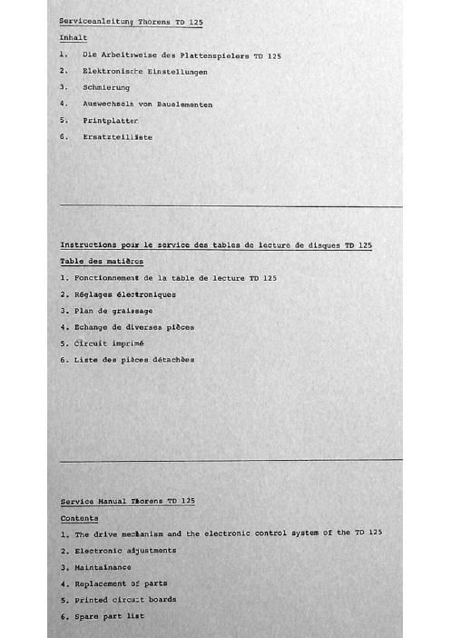
1. Die Arbeitsweise des Plattenspielers TD 125.
Des Bild l zeigt schematisch den Aufbau des Plattenspielers.

Das Hauptchassis tragt den Motor und die weiteren zum Antrieb benbtigten Aggregate.
Das Plattentellerlagcr und der Tonarm befinden sich dagegen auf dem Schwingchassis,
das durch 3 Federn mit dem Hauptchassis verbunden ist.

Der Antrieb des Plattentellers erfolgt durch einen elastischen Riemen. Somit ent-

sfiehtian keinem Punkt eine feste Verkoppelung zwischen dem Haupt- und den Schwing-
C 355 S.

Zum Antrieb wird sin lS-poliger Synchronmotor verwendet, der aus einem wechselspan-

zgngsgenerator gespeist wird. Das Bild 2 zeigt das Schaltbild dieses Steuergenera-
rs.

Es handelt sich um eine Verstererschaltung, die zuei Funktionen besitzt. Einerseits
dient sie als Verstarkungsvierpol EUr die Hienercke, andererseits ist ihre Endstufe
derart bcmessen, dass aus ihr der Motor direkt ohns weitere Verstarkung gespeist wer-
den kann. Sis besteht, wie bei NF Leistungsverstarkern aus einer eisenlosen Gegen-
taktstufe mit den Transistoren AD 149 (T5, T7), die mit Hilfe des Komplementarpaur
BC 147-BC 177 (Tl! T2) in Gegentakt angesteuert wird.

l. Ponctionnement de la table de lecture TD 125
La figure (1) illustre schématiquement la construction de cet appareil.

Le chassis principal fixe supportc le moteur et les autres elements nécessaires a
l'entralnement du plateau.

Le palier du plateau et le bras lecteur sont par contre montés sur un chassis in-
termédiaire suspendu élastiquement au chassis principal au moyen de 3 ressorts.

L'entralnsment du plateau est assuré par une courroie de caoutchouc. I1 n'existe
ainsi aucune liaison rigide entre le chassis principal et le chassis suspendu.

Le plateau est entratne par un moteur synchrone a 16 poles alimente par un oscil-
lateur. La figure (2) montre le schema de cet oscillateur.

Il s'aglt d'un circuit amplificateur a double function. D'une part il est utilise
comme quadripole d'amplification pour le pont de wien et d'autre part son etage de
sortie est dimensionné de maniére a alimenter 1e moteur directement, sans aucune
autre amplification.

L'étage de sortie, comma dans les amplificateurs de puissance BF, est composé d'un
stage push-pull sans fer, avec les transistors AD 149 (T5 et T7); 11 est commandé
en push-pull a l'aide de la paire complémentaire BC 147-36 177 (T1 at T2).

l. The drive mechanism and the electronic control system of the TD125
Pigure no. 1 shows simplified the basic design of the turntable.

The main chassis contains the motor and the further elements of the driving mechanism,
while the turntable bearing and the tonearm are situated on the spring suspended chassis.
This is connected to the main chassis by three spiral springs.

fihe turntable is driven from the motor by means of. an elastic belt, so that there is no
rigid coupling between the main and the spring suspended chassis.

'i'ho motor is a lG-pole synchronous type which is controlled by an ac generator. Figure
4116'. "'2 shows the schematic diagram of this control generator.

'31.; "i'sen amplifier circuit with two different functions. on one side it is connected to
.\ mail iagflien bridge, so that it works as an oscillator and on the other side its final stage
M f ' " nil enough to drive the motor without zurther amplification. The linal stage is

' oreerlejs push-pull amplifier with two transistors AD 19 (1'5, 17) which are fed
mlgofltary pair 11- BC 17') (1'1, '12) in push-pull.