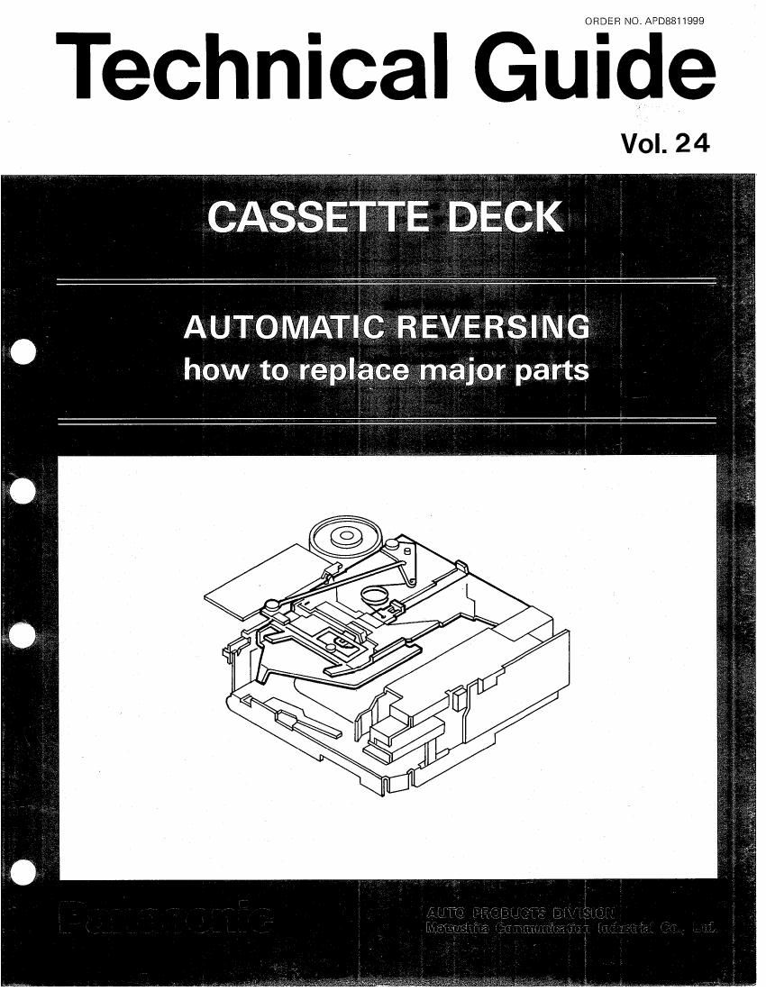
Technics Technical Cassette Deck Guide Vol.24

This is the 27 pages manual for Technics Technical Cassette Deck Guide Vol.24.
Read or download the pdf for free. If you want to contribute, please mail your pdfs to info@audioservicemanuals.com.

Page: 1 / 27
left right
Technics Technical Cassette Deck Guide Vol.24

Extracted text from Technics Technical Cassette Deck Guide Vol.24 (Ocr-read)


Page 2

-
CONTENTS

Ollow to Create Cassette Tape Loaded Condition for Service
@Reel Chassis Assembly

.Removal ................................................................................................... 4

IMounting .................................. ...................................... 5
ICassetle Pressure Assembly and Cassette Holder

.RBTTIOVZI ................................................................................................... s

-Cassette Pressure assembly and Cassette Holder Disassembly -8

Pack Slider Changing Method ------------------------------- g

IMounting ........................................................................ 10
@FR Function Assemblyfl)

IRemoval .................................................................................................. n

IMounting ................................................................................................. '2
DIER Function Assembly(2)

*Mode Selector Lever IRemoval/Mounting -------------------- -

irFR Cam Gear Illemoval/Mounting~~~
idause Lever IRemoval/Mounting~-

are Assembly IRemoval/Mounfing ........

{kMode Solenoid Assembly IRemoval/Mounting ----------------------------------------------------- 15
EPinch Roller Arm Assemblylll)

IRemovaI/Mounting ....................................................................................... 1 5
lElPineh Roller Arm Assembly(L)

IRemoval/Mounting ....................................................................................... I 7
@flywheelsfl) and (ll)

IRemoval/Mounling ------------------
Hfl Eear(LefD

IRemoval/Mounting ....................................................................................... 19
[EEK ldler Assembly

- Removal Mounting ....................................................................................... 19
IEFI Gearlllight)

I RENUVal/Mfllllltillg ....................................................................................... 2']
@Power Idler Gear and Revese Gear

I Removal / Mounting ....................................................................................... 2]

OReel Chassis Assembly Parts Replacement
ESolenoid for Ejeet

IRemuval/Mounting ....................................................................................... 22
MPower Cam Gear. Gear(3) Gearfl) Gear(2> Gear(4)

PREphnATmNs ...... 1 ......... ........................................................................... 23

fizPower Cam Gear Illemoval/Mounting- ......... 23
"Elfin" Hints ................................... Z4

*Gearll) and Gear(3) IRemovaI/Mounting-
fiSensor Gear Assembly IRemovaI/Mounting
sirlleel Assemblies(L) and (R) IllemovaI/Mounting ---------- "'26
OModels Assembled with this type CASSETTE DECK for After Markets ------------------------------------------- 27

NOTES

I Remove the deck from the set before servicing.

D For the removal of the deck from the set, refer to the Disassembly Instructions for Deck Removal ln
the Servlce Manual available for each model.

I When removing parts from the deck, carefully check beforehand how they are assembled so that
they can be properly reassembled later on;