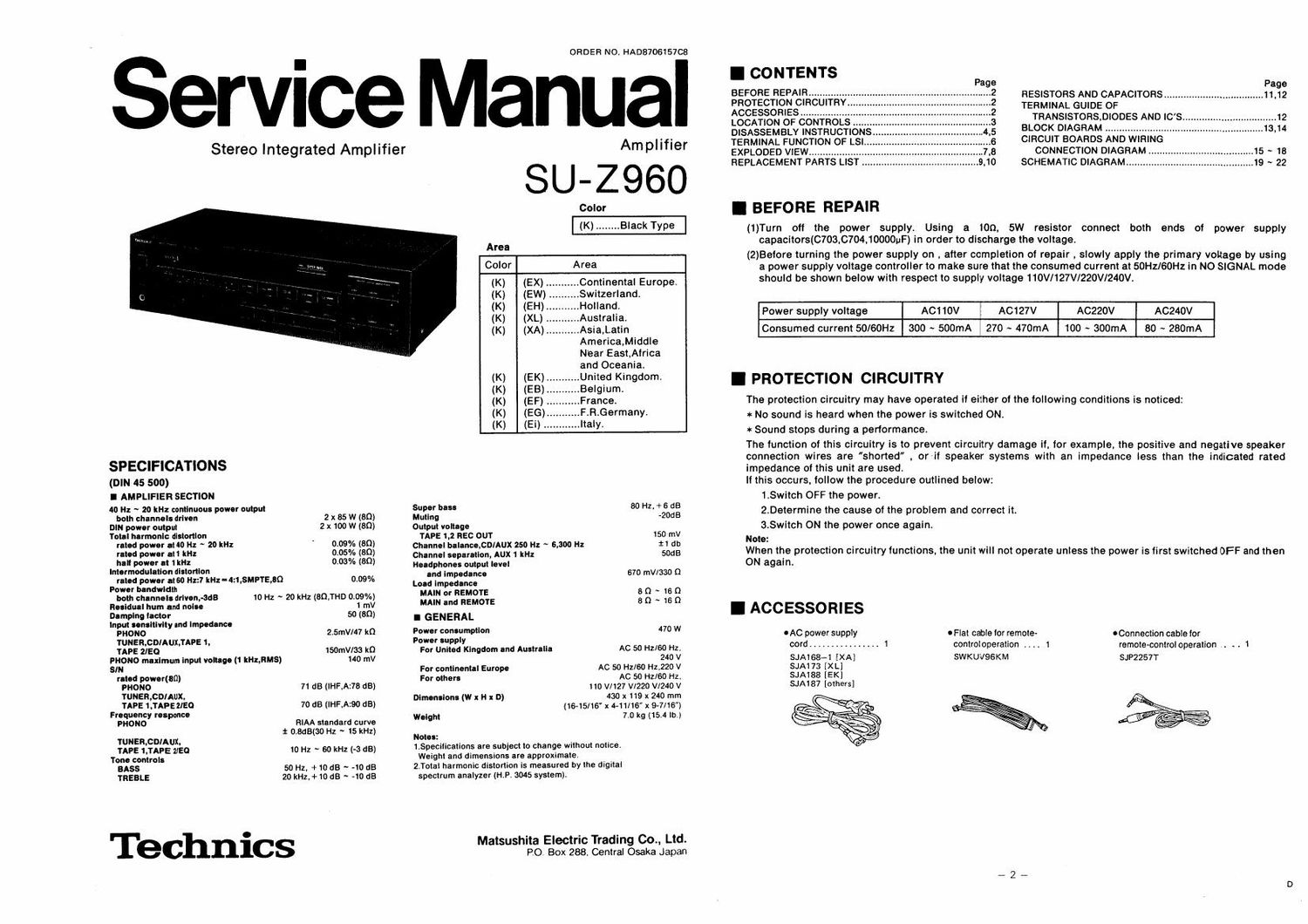
Technics SUZ 960 Service Manual

This is the 13 pages manual for Technics SUZ 960 Service Manual.
Read or download the pdf for free. If you want to contribute, please mail your pdfs to info@audioservicemanuals.com.

Page: 1 / 13
left right
Technics SUZ 960 Service Manual

Extracted text from Technics SUZ 960 Service Manual (Ocr-read)


Page 1

ORDER NO. HADB706157C8

Service Manual

I CONTENTS

BEFORE REPAIR .............
PROTECTION CIRCUITRY
ACCESSORIES
LOCATION OF CO .
DISASSEMBLY INSTRUCTIO

RESISTORS AND CAPACITORS...

TERMINAL GUIDE OF
TRANSISTORSDIODES AND ICS

BLOCK DIAGRAM ........................


. - ' ' TERMINAL FUNCTION OF LSI CIRCUIT BOARDS AND WIRING
Stereo Integrated Ampl Ierr Am pl 'f'er EXPLODED VIEW ................. CONNECTION DIAGRAM ._
S l I Z 9 6 O REPLACEMENT PARTS LIST. SCHEMATIC DIAGRAM .......

I BEFORE REPAIR

(1)Turn off the power supply. Using a 100. SW resistor connect both ends of power supply
capacitors(0703,c704.loooouF) in order to discharge the voltage.

Color

(K) .. .Black Type

Area
(2)Betore turning the power supply on , after completion of repair , slowly apply the primary voltage by using
Color Area a power supply voltage controller to make sure that the consumed current at 50Hz/60Hz in N0 SIGNAL mode
(K) (EX) ..... Continental Europe. should be shown below with respect to supply voltage 110V/127V/220Vl24ov.
(K) (EW) .. Swnzerland
(K) (EH) ..Holland
(K) (XL) ..Australia. Power supply voltage AC110V ACI27V A622OV A0240V
(K) (XA) ..Asia.Latin Consumed current 50l60Hz 300 ~ 500mA 270 ~ 470mA 100 ~ SOOmA 80 ~ 280mA
America.Middle
Near East,Atrica
and Oceania.
(K) (ex)... .,United Kingdom I PROTECTION CIRCUITRY
(K) (EB) Belglum.
(K) (EF) France. The protection circuitry may have operated it either of the following conditions is noticed:
(K) (E?) FtR.Germany. * No sound is heard when the power is switched ON.
(K) (E') ..Italy. *Sound stops during a performance.
The tunction of this circuitry is to prevent circuitry damage ii. for example, the positive and negative speaker
connection wires are shorted . or it speaker systems with an impedance less than the indicated rated
SPECIFICATIONS impedance of this unit are used.
(DIN 45 500) If this occurs, follow the procedure outlined below:
I AMPLIFIER SECTION 1.Switch OFF the power.
40 Hz ~ 20 kHz continuous power output Super base 80 Hz + 6 dB . .
ham chum." arm" 2 x 85W (80) mung -20dB 2.0etermtne the cause of the problem and correct It.
DIN power amp-II 2 x 100 w (80) Output voltage 3.Swnch ON the power once agaIn.
rot-I harmonic distortion TAPE 1,2 use our 150 "W Note'
ruled power IMO Hz ~ 20 kHz 0-09% (80) Channel balance,CDlAUX 250 Hz ~ 5.300 Hz 11 db ' . . . . , . . . .
m powuf .n m; 0.05% (80) Ohm. puma, AUX 1 ,2 sons When the protectIon olrcunry functIons. the unit WIll not operate unless the power Is tIrst sthched OFF and then
II'Izlelt awieget tdltfl'l rtl 033% (39) Headphones output level 0N again.
arm u 810" ISO on - 67D V/330 0
rated power at60 sz1 m: -4:I,3MPTE,DQ 0.09% I'd"ifn'p'gzgzg" m
Power bandwidth ~
both channels mum-368 10 Hz ~ 20 kHz (BQIHD 039%) MAIN orgsrgagfiE : 3 ~ :2 g
nun... hum and noise 1 «IV "W" 'n I ACCESSO RI ES
Demplngtector 50 (80) I GENERAL
Input sensitivity Ind Impedence 70 w
page D, TAPE 1 2.5mV/47 m :23: :zggrwflm eAC power supply 0 Flat cable tor remote- eConnection cable for
:2PE2fE30 AUX: . 150mV/33 m For United new". a Australia AC 50 Hz/GO Hz, cord ................ 1 control operation . . . . 1 remote-control operation . . .
PHONO maximum input voltage (1 ka,RMS) 140 mV 240 V SJA168-1 [XA] SWKUVQGKM SJP2257T
SIN For continental Europe AC 50 Hz/SO H2120 V SJAt 73 [XL]
mod powertsfl) For other: Ac 50 HzlGO Hz, SJAiSB [EK]
mono 71 dB (IHF.A:78 dB) no V/127 wzzo vmo v SJA187 [others]
TUNER,CDIAUX, Dimensions (W x H x D) 430 x 115 x 240 mm
TAPE LTAPHIEO 70 dB tlHF.A=90 dB) (1&15/16' x 441/16 x 94/16)
F
:33??? 8pm" RIAA standard curve Weight 7.0 kg (15.4 lb.)
t 0.8dB(30 Hz ~ 15 kHz) _
TUNER.CDIAUX, NW"

TAPE 1,TAPE ZIEQ 10 Hz ~ 60 kHz (-3 dB)
Tone controls
BASS 50 Hz, +10 (18 ~ -10 dB

TREBLE 20 kHz, + 10 63 ~ 40 dB

Technics

1.3pecilications are subject to change without notice.
Weight and dimensions are approximate.

2.Total harmonic distortion is measured by the digital
spectrum analyzer (H.P. 3045 system).

Matsushita Electric Trading 00., Ltd.
PO. Box 288. Central Osaka Japan

Page 2

36157C8

lifier

30

rope.

+6 dB
4008

I50 mV
:1 db
50615

([330 0

~16()
~160

470 W

[60 Hz.

240 V
1220 V
160 Hz,
V/240 V
240 mm
)-7/16")
|5.4 lb )

u, Ltd.
1 Japan

I CONTENTS

BEFORE REPAIR .............
PROTECTION CIRCUITRY
ACCESSORIES ...............
LOCATION OF CONTROLS
DISASSEMBLY INSTRUCTIONS
TERMINAL FUNCTION OF LSI
EXPLODED VIEW ................
REPLACEMENT PARTS LIST .

I BEFORE REPAIR

Page

RESISTORS AND CAPACITORS .................................... 11,12
TERMINAL GUIDE OF

TRANSISTORSDIODES AND ICS. ..... 12

BLOCK DIAGRAM ............................. 13.14
CIRCUIT BOARDS AND WIRING

CONNECTION DIAGRAM .15 ~ 18
SCHEMATIC DIAGRAM ........ .19 ~ 22

(1)Turn off the power supply. Using a ton, 5W resistor connect both ends of power supply
capacitors(C703,C704.10000uF) in order to discharge the voltage.

(2)Betore turning the power supply on , atter completion ot repair . slowly apply the primary voltage by using
a power supply voltage controller to make sure that the consumed current at 50Hz/60Hz in NO SIGNAL mode
should be shown below with respect to supply voltage 110V/127V/220V/240V.

Power supply voltage ACttOV

ACI 27V

ACZZOV ACZ40V

Consumed current 50/60Hz 300 ~ SOOmA

270 - 470mA

100 ~ 300mA 80 ~ 280mA

I PROTECTION CIRCUITRY

The protection circuitry may have operated it either of the tollowing conditions is noticed:

* No sound is heard when the power is switched ON.
* Sound stops during a performance.

The tunction of this circuitry is to prevent circuitry damage it, for example, the positive and negative speaker
connection wires are shorted , or-it speaker systems with an impedance less than the indicated rated

impedance of this unit are used.
It this occurs, follow the procedure outlined below:

1.Switch OFF the power.

2.Determine the cause of the problem and correct it.

3.Switch ON the power once again.

Note:
When the protection circuitry functions. the unit will not operate unless the power is first switched OFF and then
0N again.
OAC power supply - Flat cable for remote- - Connection cable lor

cord ................ 1 control operation .. ,. 1 remote-control operation I. . . 1

SJA168-1 [XA] SWKUVQSKM SJP2257T

SJA173 [XL]

SJA188 [EK]

SJA187 [others]