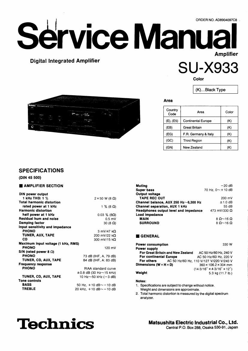
Technics SUX 933 Service Manual

This is the 23 pages manual for Technics SUX 933 Service Manual.
Read or download the pdf for free. If you want to contribute, please mail your pdfs to info@audioservicemanuals.com.

Page: 1 / 23
left right
Technics SUX 933 Service Manual

Extracted text from Technics SUX 933 Service Manual (Ocr-read)


Page 2

m ,

l CONTENTS I LOCATION OF CONTROLS
Page

EEFORE REPAIR PRINTED CIRCUIT BOARDS ........................ 17~21 . Front pa nel

ROTECTION CIRCUITRY . . TERMINAL GUIDE OF IC'S,

tCCESSORIES TRANSISTORS AND DIODES .......................... 21

.OCATION OF CONTROLS ............. WIRING CONNECTION DIAGRAM .................. 22

)ONNECTIONS ................ DESCRIPTION OF FL PANEL . . . . . 23

)ISASSEMBLYINSTRUCTIONS . . FUNCTIONS OF IC TERMINALS . . 23, 24

ECHEMATICDIAGRAM .......... REPLACEMENT PARTS LIST . 25~33

SLOCK DIAGRAM EXPLODED VIEW ...... . 31, 32

l BEFORE REPAIR

(1) Turn off the power supply. Using a 100, 5 W resistor connect both ends of power supply capacitors (C71 1 , C712, 3300 pF) in
order to discharge the voltage. '

(2) Before turning the power supply on, after completion of repair, slowly apply the primary voltage by using a power supply
voltage controller to make sure that the consumed current at 50 Hz/60 Hz in NO SIGNAL mode should be shown below with
respect to supply voltage 110 W127 V/22O V/240 V.

Power supply voltage AC 110 V AC 127 V AC 220 V AC 240 V
Consumed current 50 Hz 100~5oo mA 7o~47o mA so~2so mA 40~240 mA E Power swttch (POWER) Audio muting switch (MUTING)
Consum9d current 50 HZ 97475 "A 63"457 "A 49444 mA 39~236 mA El Volume level/balance indicator Balance controls (BALANCE)
(BALANCENOLUME)
IE] Tone controls (BASS/TREBLE)
El Volume-levelindicator
Super bass control (SUPER BASS)
I PROTECTION CIRCUITRY E Mutingindicator(MUTlNG) IE
. . . . . . .. . . Surround-sound switch (SURROUND)
The protection crrcurtry may have operated :1 either of the followmg conditions is noticed:
No sound is heard when the power is switched ON. E] Volume control (VOLUME)

Sound stops during a performance. [El Headphones jack (PHONES)

The function of this circuitry is to prevent circuitry damage it. for example. the positive and negative speaker connection wires are
shorted", or if speaker systems with an impedance less than the indicated rated impedance of this unit are used.
If this oocurs, follow the procedure outlined below: .Rear panel
1. Switch OFF the power.
2. Determine the cause of the problem and correct it.
3. Switch ON the power once again.

[E Input selectors/indicators

Note: FLAVBMKW COOLING FAN
' ' ' ' ' ' TAPE (REMOTE OUT)
When the protection circurtry functions, the unit Will not operate unless the power us first swrtched OFF and then 0N again. REC ourl TO DECK [-sunnouno-souuo~
(REMOTE m) SPEAKERS
[-PHONO To TUNER TUNER GND \ LMArN *
I ACCESSORIES l 8
AC OUTLET
OAC power supply cord .............. 1 OAttachmenI AC plug ............................. . 1
f' uration ofAC wersu | cord dI ers aocordin to area. _
Con I9 90 ppy 9 [( C) C) )l W I

SJA190 .......... For (GN) area only. SJP9215...For ((36) area only

SJA168 .......... For(EB)areaonly. D ~Ac IN

FtJA0004 ........ For (60) area only.

SFDACOSE03 ....Forothers.

$9
s~isn
~TURNTABLE 1 [-l
co [- lNPUT- SYNCHRO-REC
;
Aux EXT c D worms: sELEclrof
LOUTPUT -SYNCHRO TAPE (Fortoclwoamy
To DECK
(Except [EG] area)

Phono input capacitance is about 270 pF tor EG area
(about 100 pF tor other areas).