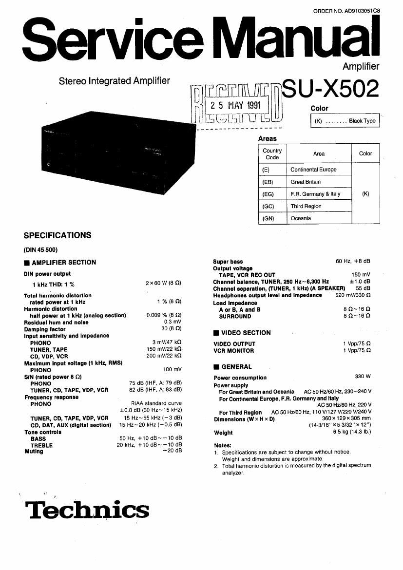
Technics SUX 502 Service Manual

This is the 42 pages manual for Technics SUX 502 Service Manual.
Read or download the pdf for free. If you want to contribute, please mail your pdfs to info@audioservicemanuals.com.

Page: 1 / 42
left right
Technics SUX 502 Service Manual

Extracted text from Technics SUX 502 Service Manual (Ocr-read)


Page 1

ORDER NO. A0910305108

ervice Manual

Amplifier
Stereo Integrated Amplifier
mini] U-X502
5 my 1991 Colo.
iii IU LE
I J (K) ........ Black Type
Areas
Country
Code Area Color
(E) Continental Europe
(EB) Great Britain
(EG) F.Fi, Germany 8: Italy (K)
(GO) Third Region
(GN) Oceania
SPECIFICATIONS
(DIN 45 500)
I AMPLIFIER SECTION Super has; 60 Hz. +8 dB
Output voltage
9' WW 9' TAPE, vcn use our 150 mV
1 kHz THD: 1 % 2x60 W (8 0) Channel blIlncO, TUNER, 250 Hz~6,300 Hz :I:1.0 dB
. . Channel separation, (TUNER, 1 kH:)(A SPEAKER) 55 dB
Total harmonic distortion Headphones output level and Impedance 520 mwsao (1
rated power at 1 kHz 1 % (8 0) Load Impedance
Harmonic distortion A or B, A and a 5 n~15 0
null power at 1 kHz (analog section) 0.009 % (8 fl) SURROUND 8 Q~16 I)
Rosidunl hum and noise 0.3 mV
Damping lactor 30 (8 n)
Input sensitivity and Impedance I VIDEO SECTION
WOW 3 "W7 *9 VIDEO OUTPUT 1 v n
TUNER, TAPE 150 mm kn vcn MONITOR 1 (gs/7:3
CD, VDP, VCR 200 mil/22 kfl
Maximum Input voltage (1 kHz, HMS)
mono 100 mV I GENERAL
SIN (rated power 3 9) Power consumption 33° W
PHONO 75 d8 (IHF, A: 79 dB) Powersupply
ligacrfipmtfi' V?! m 82 dB HE A: 83 BI For Great Britain and Oceania AC so Hz/eo Hz, 230~24o v
PH ON 0 RIAA standard curve For Continental Europe, F.H. Germany 122332160 Hz 220 V
*0'8 dB 30 ZN I 5 kHz) For Third Region AC 50 Hz/60 Hz, 110 v11 27 v1220 v124o v
TUNER, CD, TAPE. VDP, VCR 15 H2~55 kHz (-3 dB) Dimensions (w x H x D) 360x 129x 305 mm
co, DAT, AUX (digital section) 15 Hz~2o kHz (-05 dB) (14-3116 X53132" x 12")
Tone controls Weight 6.5 kg (14.3 lb.)
BASS 50 HZ, +10dB~-1O dB
TREBLE 20 kHz. +10 dB~ -10 dB Notes:
Muting 20 dB 1. Specifications are subject to change without notice.

Weight and dimensions are approximate,
2. Total harmonic distortion is measured by the digital spectrum
analyzer.

Téchnics

Page 2

su-xsoz

I CONTENTS


Page

Before repairs ..... Description of FL panel .................................. 21
Protection circuitry . Circuit board diagram ..................... 22~27
Accessories ..... Terminal guide of lCs, transistors and diodes .......... 27
Location of controls . . . Wiring connection diagram ..................... . 26
Connections ............... 4N7 Function of IC terminals . . . 29, 30
Digitalization of audio signals . . 8 Block diagram ......... 31~33
Disassembly instructions. . . 9~12 Replacement parts list ..... _ 3449, 42
Schematic diagram . . . . ...................... 13~21 Cabinet parts list .............. 40. 41
Packaging ............................................. 42

I BEFORE REPAIR

(1) Turn off the power supply. Using a 10!), 5 W resistor connect both ends of power supply capacitors (C711, C712. 3300 pF) in order to discharge the
voltage.

(2) Before tuming the power supply an. alter completion of repair, slowly apply the primary voltage by using a power supply voltage controller lo make
sure that the consumed current at 50 Hz/GO Hz in N0 SIGNAL mode should be shown below with respect to supply voltage 1 10 V/127 V/220 V/

240 V.
Power supply voltage AC 1 10 V AC 120 V AC 220 V AC 230 V AC 240 V
Consumed current 50 Hz 323~754 mA 297~694 mA 160~373 mA 154~360 mA 146~341 mA
Consumed current 60 Hz 316~737 mA 291~679 mA 156~365 rnA 150~351 mA 144~336 mA

I PROTECTION CIRCUITRY

The protection circuitry may have operated if either of the following conditions is noticed:
'No sound is heard when the power is switched ON.
'Scund stops during a performance.
The function of this circuitry is to prevent circuitry damage If, for example. the postive and negative speaker connection wires are shorted", or if speaker
systems with an impedance less than the indicated rated impedance of this unit are used.
If this occurs, follow the procedure outlined below:
1. Switch OFF the power.
2. Determine lhe cause of the problem and correct it.
3. Switch ON the power once again.
Note:
When the protection circuitry functions, the unit will not operate unless the power is first switched OFF and then 0N AGAIN.

I ACCESSORIES

0AC power supply cord .................................... 1 oAC plug adaptor .......................................... 1
Configuration of AC power supply cord differs according to area.

SJA187 .......... For (E) (EG) area only. SJ P921 5 ........ For (60) area only.
SJA173. . . . For (GN) area only
SJA185. . For (EB) area only.
FlJA0004 . . For (GO) area only.

SFDACOSEOS . . . . For others.