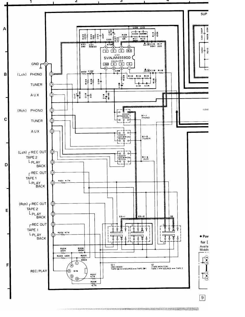
Technics SUX 2 Schematics

This is the 3 pages manual for Technics SUX 2 Schematics.
Read or download the pdf for free. If you want to contribute, please mail your pdfs to info@audioservicemanuals.com.

Page: 1 / 3
left right
Technics SUX 2 Schematics

Extracted text from Technics SUX 2 Schematics (Ocr-read)


Page 2

9 I ° l
# - -
- -
SUP |897OB r SUP l897OA
'52."; lHlGH FILYER) m a
fi n x _ E g
3 é a 2 g § 1 a
n _ x - N H 5 -
2: a _ n ~ 5
3 g I . . '1 Eng g ,6 ,0. AN 7060 m 1m
:7 low: "I. c > sa
N ' J2: T 5 0 0 9 0-0-0...o
2:: E _ " D 6 a m can 'n
u . z :5 I > .. ' w E
rm: 3 - I §3 3 5
. J 55357 2 not! 5 + J'T z n . cats 2|
t-i 2 3 . ¢ :3 :EN n '--|
:3?! "a, "C! :3": I209 i."
an u *
x
_ - 39 "or __;.. 2,. «2r:
'- ss': 21°: - 32 =2 '
- 9" '_'x
were: isa
m- d u -
a l I
9 Q 6 ® 0 Q @ as «a 2°
- . » m
j: , a: l
(2 cu
. "11 "m
$0 | onoorq -
lLOuDNESSlI HI
LL
0
3
x IC so: AN7060 am rows
- __ __ _ a 1:1 [E E El E] m a E
I 2 s a s s 7 a s
305
c l: a%
. . x
035: #5 %E can an
1. 51-1 ~ 81-3: Input selector switch in "phono"position. g 1:; -
(phonoA-vtunerHauxl 3 U §_;
2. $2: Tape monitor switch in "source" position. . lace no: oi
(tape 1... source -» tape 2) S u a: E
3. 531, 83-2: Recording mode switch in "source" position. " * '° ° "
(tape 1 >2 Hsource (atape 2 >1! lg 9
4. 84: Remote speaker switch in "off" position. ,. .4 TC ,1 3 N
5. S Main speaker switch in on" position. 21 " kg 0
6. $6: Loudness switch in "off" position. E5 5; E
7. 57: High filter switch in off" position. ' ) E 9.6 )V
8. SS: Subsonic filter switch in "off" position. N K n 1
9. 89: Voltage adjust switch in "240V" position. 51 G?
240V *-~ 220V H HOV H120V
10. 510: Power source switch in "on" position, '7**-
1LE Indicated voltage values are the standard values for the owl
unit measured by the DC electronic circuit tester lhigh- l/Z 2?; nqoz [E
impedance) with the chassis taken as standard. , = n
Therefore] there may exist some errors in the voltage §A , Q; -. a,
values, depending on the internal impedance of the a : mg 3: no: 3
DC circuit tester, 3 a no K
ll 12. Signal lines of left channel 040: "0 E
- Positive ( 6-) l voltage lines °°'-°2-° 1 ~
_ 13. A indicates that only parts specified by the 2§vanclHowlcs E] §§§F§
l manufacturer be used for safety. 0 m
i zsc I685 E1
' 0 Power source circuit for [XA] and [XAL] SW'YCNNG El
. .I 0.02.40:
for [XA] for [XAL] MA |50 .x
Available in Asia, Latin America, Available in Australia. g:
Midd'eea""°' _l -| l______
owl Nmtiv
A ' . A AC . MA I062
,_ AC
up LINE LINE 040L405) 9405.401
120/110/ 120/110/ SVDSRIKZ MA||50
220/240v I I . _ 220/240V
(SO/GOHZ) at l50/60H2l
- ______---J -_---__J