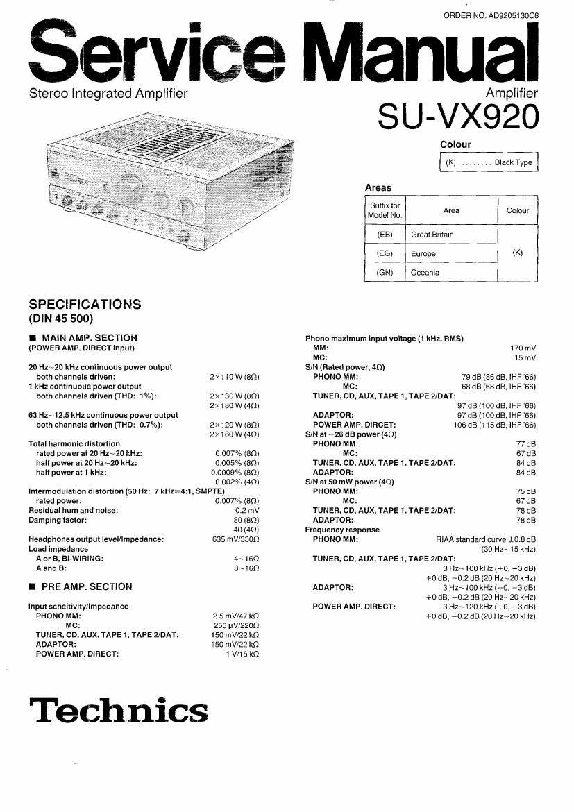
Technics SUVX 920 Service Manual

This is the 16 pages manual for Technics SUVX 920 Service Manual.
Read or download the pdf for free. If you want to contribute, please mail your pdfs to info@audioservicemanuals.com.

Page: 1 / 16
left right
Technics SUVX 920 Service Manual

Extracted text from Technics SUVX 920 Service Manual (Ocr-read)


Page 2

su-wzo

Tone contrls

BASS: 50 Hz, +10~-10dB

TREBLE: 20 kHz, +10~-10dB
Mutlng: -20 dB
Subsonic filter: 20 Hz, -12 dB/oct
Loudness control (volume at -30 dB): 50 Hz. +9 dB
Output voltage

TAPE 1, TAPE 2IDAT REC OUT: 150 mV
Channel balance, (AUX 250 Hz~6.3 kHz): :1 dB

Channel separation (AUX 1 kHz): 50 dB

I CONTENTS

BEFORE PEPAIR AND ADJUSTMENT

PROTECTION CIRCUITRY ....... . 2
LOCATION OF CONTROLS . . 3
ACCESSORY ........... . 4
CONNECTIONS ......... .4~6

DISASSEMBLY INSTRUCTIONS
MEASUREMENTS ANDADJUSTMENTS . ..

I GENERAL

Power consumption: 440 W
Power supply: AC 50 H2160 Hz, 230/240 V
Dimensions (WXHXD): 430x158x429 mm
Weight: 16.5 kg
Notes:

1 . Specifications are subject to change without notice.
2. Weight and dimensions are approximate.
3. Total harmonic distortion is measured by the digital spectrum


analyzer,
BLOCK DIAGRAM
SCHEMATIC DIAGRAM . .. 13~17
PRINTED CIRCUIT BOARDS . . 18~21
WIRING CONNECTION DIAGRAM ..... 22
REPLACEMENT PARTS LIST . . . 23~26, 29

CABINET PARTS LOCATION
PACKAGING .................

27,28
30

I BEFORE REPAIR AND ADJUSTMENT

(1) Turn off the power supply. Using a 1 on, 10 W resistor, shortcircuit both ends of power supply capacitors (0601 , C602) in

order to discharge the voltage.
(2) Before turning on the power switch of the unit.
A. Connect the voltage controller to the primary side.

B. Connect the AC ampere meter to the primary side or connect the DC voltage meter to the i3 circuit of the secondary

side.

C. Turn the VR of ICC (VR451. VR452, VR501 and VR502) to minimum (counterclockwise).
D. After setting the output to zero of the voltage controller, turn on the power switch of the unit.

And increase the output of voltage controller gradually.

Then, check carefully whether the current value of primary side become more than following value or whether the DC

voltage of secondary side is increasing slowly.

E. If the value of current is increasing unusually or the DC voltage is not increasing, lower the output level of voltage

controller immediately.

OThe current value of the primary side at no signal. (Confirm the power supply voltage of each area and provided voltage of

the unit.)
Power supply voltage AC 230 V Ac 240 V
50 Hz
Consumed current 150~450 mA 140N430 mA
60 Hz

I PROTECTION CIRCUITRY

The protection circuitry of the amplifier may have operated it either of
the following conditions is noticed:

0N0 sound isheard when the power is turned on.

OSound stops during a performance.

The function of this circuitry is to prevent circuitry damage if, for
example, the positive and negative speaker connection wires are
shorted, or if speaker systems with an impedance less than the
indicated rated impedance of the amplifier are used.

If this occurs, follow the procedure outlined below:

1 , Turn off the power.

2. Determine the cause of the problem and correct it.
3. Turn on the power once again.

Note:
When the protection circuitry functions, the unit will not operate
unless the power is first turned off and then on again.