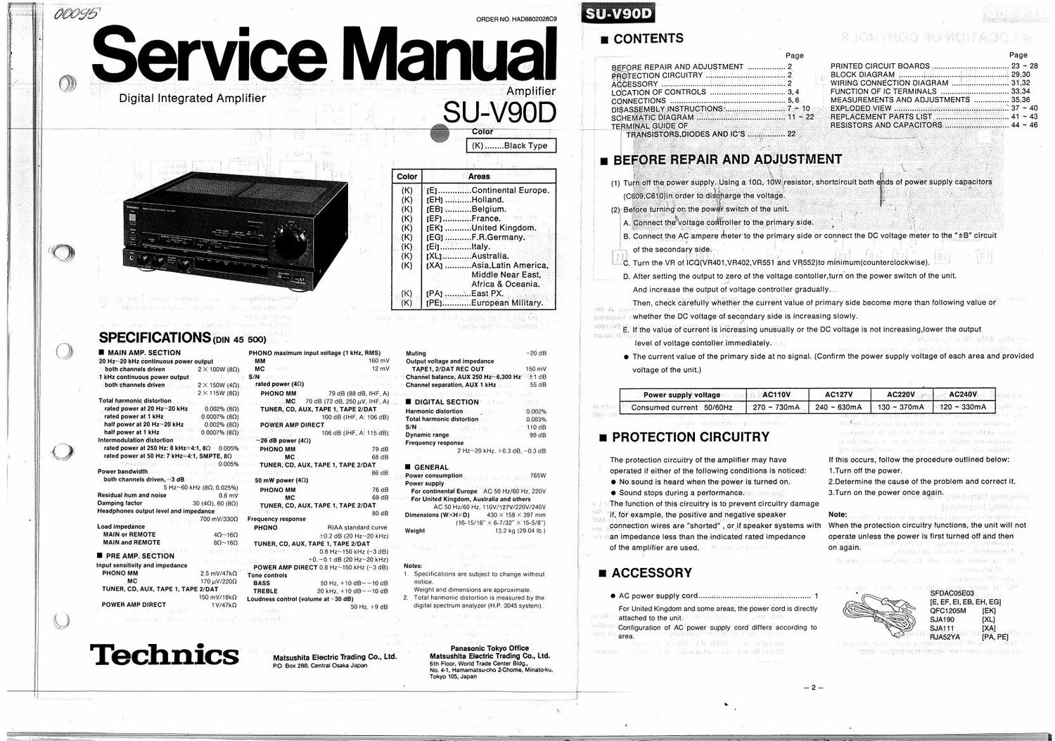
Technics SUV 90 D Service Manual

This is the 26 pages manual for Technics SUV 90 D Service Manual.
Read or download the pdf for free. If you want to contribute, please mail your pdfs to info@audioservicemanuals.com.

Page: 1 / 26
left right
Technics SUV 90 D Service Manual

Extracted text from Technics SUV 90 D Service Manual (Ocr-read)


Page 1

Digital Integrated Amplifier

ORDER NO HAD8802028CS

SerVIce Manual

Amplifier

SU-V9OD

COIOI

SPECIFICATIONS (pm 45500) I i

I MAIN AMP. SECTION
20 Hz~20 kHz continuous power output
-- both channels driven 2 X 100W (80)
1 kHz continuous power output
- both channels driven _ 2 X 150W (40)
~ 2 >< 115w (80)
Total harmonic distortion
rated power at 20 Hz~20 kHz
I rated power at 1 kHz
hall power at 20 Hz~20 kHz
hall power an kHz
Intermodulationdistortion
rated power at 250 Hz' 8 kHz-4:1,8Q 0.005%
rated power at 50 Hz: 7 kHz=4: 1, SMPTE, 80
0. 005%

0.002% (an),
0.0mm (em
0.902% (80)
ocean/Item

Power bandwidth
both channels driven. 3 dB
5 Hz~60 kHz (80, 0.025%)

Residual hum and noise 0 8 mV
Damping lactor 30 (40). 60 (80)
Headphones output level and impedance
_ _ 700 mV/aaon
Load impedance
MAIN or REMOTE AQ~1SQ
MAIN and REMOTE 80~16n
I PRE AMP. SECTION
Input sensitivity and Impedance
PHONO MM 2 5 mV/47k0'
, MC 170 uV/ZZOQ
TUNER, CD, AUX, TAPE 1, TAPE 2/DAT
150 mV/18kfl
POWER AMP DIRECT

1 W47)

Technics

PHONO maximum input voltage (1 kHz, HMS)

MM 160 mV
MC 12 mV

S/N '
rated power (40)

PHONO MM 79 dB (88 dB, IHF, A)
, ~MC 70 dB (72 dB, 250 LIV. IHF, A)
TUNER. CD. AUX. TAPE 1. TAPE 2/DAT ,
100 dB (ll-IF. A: 106 dB)
POWER AMP DIRECT
106 dB (it-IF A: 115 dB)

26 dB power (40)
PHONOMM 79 dB
MC 68 dB
TUNER,CD, AUX. TAPE 1, TAPE 2/DAT
, - 86 dB
50 mw power (40)
PHONO MM 76 dB
MC 59 dB
TUNER, CD, AUX. TAPE 1 TAPE 2/DAT
80 dB

Frequency response
PHONO RIAA standard curve
+0 2 dB (20 Hz~20 kHz)
TUNER, CD AUX, TAPE 1, TAPE 2/DAT
0 8 Hz~150 kHz (-3 dB)
+0. 0.1 dB (20 Hz~20 kHz)
POWER AMP DIRECT 0 8 HZ~150 kHz (-3 dB)
Tone controls
BASS 50 HZ, +10dB~-10dB
TREBLE 20 kHz, +10dBN-10 dB
Loudness control (volume at 730 dB]
50 HZ, +9 (33

Malsushita Electric Trading 00.. Ltd.

20. Box 288. Central Osaka Japan

Color :Areas

(K) Continental Europe.

(K) Holland.

(K) ..Belgium.

(K)

(K)

(K)
,_ (K).
(K) ,
(K) ..Asia,l.atin America;
Middle Near East,
Africa & Oceania.

(K) East PX. __ .

(K) European Military
Muling *20 dB
Output voltage and impedance

TAPE1, 2/DAT REC OUT 150 mV
Channel balance; AUX 250 Hzr~6, 300 Hz +1 dB
Channel separation, AUX 1 kHz . 55 dB
I DIGITAL SECTION
Harmonic distortion 0.002%
Total harmonic distortion 0.003%
S/N , , 110 115
Dynamic range 99 dB

Frequency response
2 HZ~20 kHz. +0.3 (:18. '03 £13

I GENERAL
«1 Power consumption . 765W
Power supply
For continental Europe AC 50 Hz/GO Hz, 220V
For United Kingdom. Australia and others
AC 50 I'll/60 Hz, 110V/127V/220V/240V
Dimensions (WXHXD) 430 X 158 X 397 mm
(16-15/16" X 6-7/32" >< 15-5/8"}

Weight 13.2 kg (2904 lb)

Notes:

1. Specifications are subject to change without
notice.

Weight and dimensions are approximate.
2, Total harmonic distortion is measured by the
digital spectrum analyzer (HP. 3045 system].

Panasonic Tokyo Ottico

6th Floor. World Trade Center Bldg,

No. 4-1, Hamamatsu-cho Zchome. Minatoku,

Tokyo 105, Japan

Matsushita Electric Trading Co., Ltd.

5-

i CONTENTS


PRINTED CIRCUIT BOARDS
BLOCK DIAGRAM i .....


BEFORE REPAIR AND ADJUSTMENT
PROTECTION CIRCUITRY


ACCESSORY ................. WIRING CONNECTION DIAGRAM 31,32
LOCATION OF CONTROLS . FUNCTION OF IC TERMINALS ..... 33,34
CONNECTIONS MEASUREMENTS AND ADJUSTMENTS 35.36
DI$AS EXPLODED VIEW > 37 ~ 40

nEsisTons AND

B. Connect the ACampere rheterto the primary side or connect the DC voltage meter to thefts circuit

of the secondary . . .
- Turn the VR oi ICQ(VR401, VH402 VR551 and VR552)to mInImum(counterclockmse)
D. After setting the output to zero of the voltage contoller,turn on the power switch of the unit.

And increase the output of voltage controller gradually
Then. check carefully whether the current value of primary side become more than following value or

whether the DC voltage of secondary side IS increasing slowly.
E. It the value of current is increasing unusually or the DC voltage Is not increasing, lower the output

level of voltage contoller immediately
0 The current value of the primary side at no signal. (Confirm the power supply voltage of each area and provided

voltage of the unit.)

* AC240V .
1.120 ~ 330mA

ACZ20V ,r,
- 130 ~ 370mA

AC127V
240 ~ 630mA

, ,IACIIOV
270 ~ 730mA._

Power slipplyi voltage
Consumed current 50/60Hz

I PROTECTION CIRCUITRY i

The protection circuitry of the amplilier may have
operated if either of the following conditions Is noticed:

o No sound is heard when thepower is turned on.

0 Sound stops during a performances;

The function of this circuitry is to prevent circuitry damage
'if, for example, the positive and negative speaker Note:
connection wires are shorted or it speaker systems with When the protection circuitry functions, the unit will not

, an impedance less than the indicated rated impedance operate unless the power is first turned off and then
of the amplifier are used. on again. , _ ' _. _,

if this occurs, iollow the procedure outlined below:
1.Turn oil the power.

2.Determine the cause of the problem and correct it.
3.Turn on the power once again.

I ACCESSORY

0 AC power supply cord ......
For United Kingdom and some areas, the power cord Is directly

SFDAcoseoa' ' ,
IE, EF, El, E8, EH, EG]
QFCi205M {EK}

attached to the unit SJA190 [XL]
_ Configuration of AC power supply cord dillers according to $JA111 [XA]
area FIJA52YA [PA, PE]

Page 2

I LOCATION OF CONTROLS

a, WW

II Irwin. MW


olive
servo a-I Ftectiiier - Power trans.
power supply _


Class AA To each circuit To each circuIt
bullet
om "9
convevler Power Amp Direct
'Piidno cartridge digitallanalog
. SeieClOLr \ selector Tone control
. switch
dIIecl switch Mamk
o 5993 e!
V i
,ANALOG lNFZUI , Mum c253? Speaker] am
> , ower am
PHONOH L lhput/ PI " Switch 9XIE5"°'Y *. ' :mlaclohp
runways > . reaming. I, V lLorDcWer . muIIng'circuiI Remote
« .: cow I games ": . . speaker
Aux _ selectors I W
TAPE I ., _I L
Loudness
Swllch
«i

TAPE 2IDATO-+

III Power switchtpower) _

lZl Speaker selectors (speakers)
These selectors are used to turn the speaker systems on and
3 off -

El Operation indicator (operation)

I This indicator illuminates approximately 5 seconds after the
1 power is switched ON indicating that this unit is in the opera-
tional condition, it there is any abnormal condition oi the out-
put signals to the speaker systems (such as. for example, a
short-circuit of the speaker connection wires. etc.). this abnor-
mal condition will be detected. the protection circuitry will
function. and this indicator will stop illumination. _

LTJSampling frequency indicators
(sampling frequency)
These indicators function to illuminate to indicate the detec-

tion of the sampling irequencyoi the digital signals input to the :

DIGITAL INPUT" terminals on the rear panel oi this unit.

(illumination occurs when digital signals are received even a

digital component is not in the play mode.)

32 kHz: For digital signals with the sampling lrequency oi
32 kHz mode

44.1 IIsz CD and others

48 kHz: For digital signals with the sampling frequency of
48 kHz Inode

El Audio, muting switch (muting) L
Set to the -20 dB" position when a disc is being changed or
to temporarily reduce the volume level (approx, 1/10).

, ESL] Loudness switch (loudness)

Set to the L'on position when listening to music at low
volume. Auditory Iperceptidn of sound in the low frequency
range falls off at low volume but when theswitch IS in this post»

L tLloLrI. thlsL delICIency IS compensated for sothat the lull Impact

of the musical performance can be enjoyed.

II Digital input selector (digital input)

This selector Is used when a component connected to one of
the DlGlTAL lNPUT" terminals (on the rear panel of this unit)
is to be used as the sound source.

I ElPower amlellieLrL direct switch/indicator

(power amp direct)

When this switch is switched ONI (indicator will illuminate ),a

superior level of tone quality can be obtained because the
signals from the component connected to the POWER AMP

DIRECT terminals or the DIGITAL INPUT" terminals are
I sent directly to the sound volume without passing through the

tone control circuit etc. of this unit

IE Digital/analog selectorllndlcators
. (digital/analog)

This selector is used (when the power amp direct is ON) to

, select asthe signaisource. either the component connected

to the DlGlTAL lNPUT" terminals or the component con-
nected to the POWER AMP DIRECT" terminals.
One oi the indicators will indicate which source is selected

@lVolume control/Indicat L

There are two types oi volume scale indications: one tor when
the power amp direct is OFF. and one for when it is ON/
(Indicator will illuminate. ).

El PLhono cartridge elector (phono selector)

This selector should be set to the position which corresponds
to the type ol cartridge used on the turntable

MM (- I): Set to this position when using a moving magnet -

type cartridge or high- output moving- -coLi| car-
tridge (1 mV or more)

MC(1- -): Set to this position when using a moving- -coil
type cartridge '

[I Recording output signal indicators

(recording selector) , , I
These indicators indicate the sound source which can be
recorded I

Input signal indicators (input selector)

These indicators indicate the sound source oi the sound being
heard lrom the speakers. -

lnputlrecording-source selectors

Press to select the sound source to be listened to and/or the
sound source to be recorded.

Note that the function of these selectors changes depending
upon the setting of the recording-mode selector.

(Refer to "Hecmdingvmode selector/indicator")

L EilRecording-mode selector/indicator (rec mode)

, sound source to be listened to and the recording sound

This selector is used to select the signal to be recorded by the
connected tape deck.

When this selector is pressed, the indicator flashes ON and
OFF repeatedly; when one of the input/recording source selec-
tor is then pressed this indicator changes from

Itlashihg to a

. steady illumination.

ll this selector is pressed while one Lot thLLe Liecording output
signal indicators is illuminated, the recording- mode indicator
will change lrom a steady illumination to repeated flashing;

L when it is pressed once again. the indicator will be extinguish-
\ed . _
~When the recording- -rnode indicator Is not illuminate L

Lll one of the input/reCOrding source selectors is press

In both be switched at the same time. ,
When the recording-mode indicator is flashing:

it one of the input/recording source selectors Is pressed only
the recording sound: source _WIl| be switched.

, When the recording-mode indicator is illuminated:

it one oi the input/recording source selectors ls presse only
the sound source to be listened to will be switched I'-

LL Balance control (balance): _ I

"the

This entrol is usedto adjust left/right volume balance.

L Tone control switch (tone control)

Set this switch to the on position you Want toL adiust

' or tone quality.

- lTone controls (bass/treble)

Headphones jack (phones)

The bass control isLlor the low-lquuency sound range. and the
treble control is for the high-frequency sound range.

w/