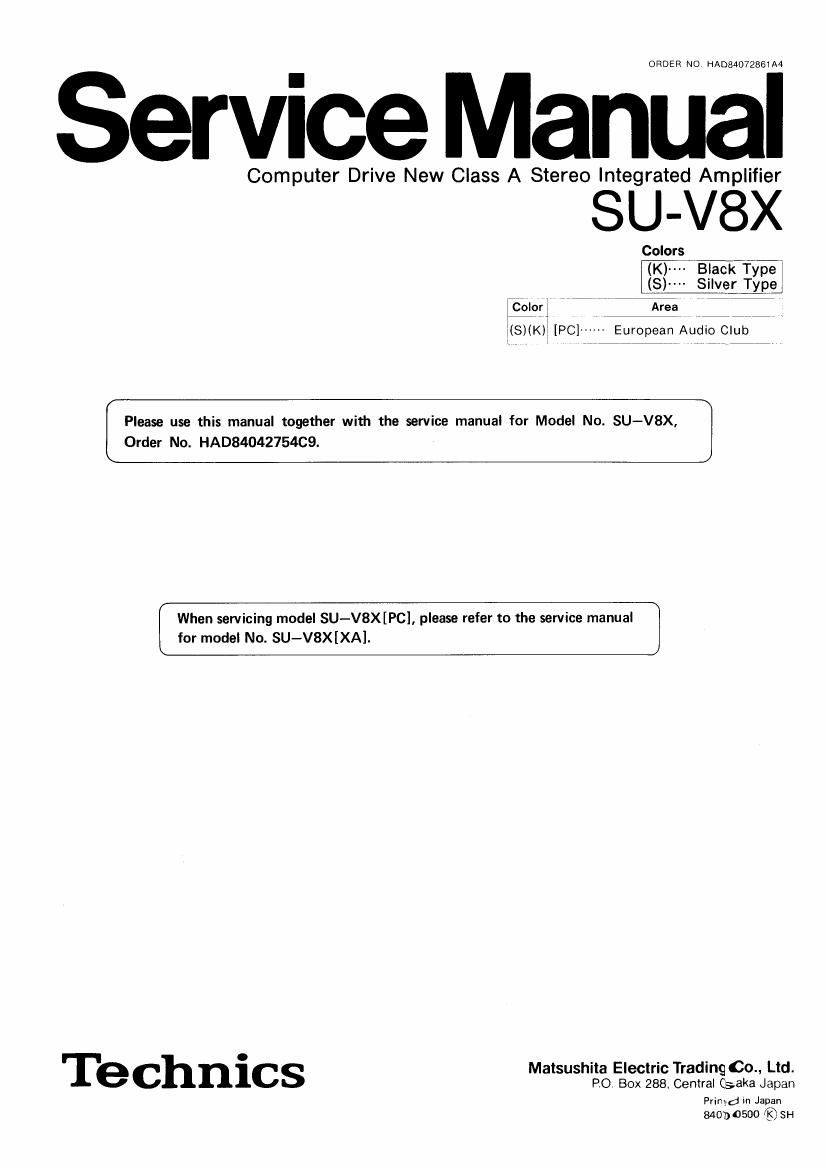
Technics SUV 8 X Service Manual

This is the 13 pages manual for Technics SUV 8 X Service Manual.
Read or download the pdf for free. If you want to contribute, please mail your pdfs to info@audioservicemanuals.com.

Page: 1 / 13
left right
Technics SUV 8 X Service Manual

Extracted text from Technics SUV 8 X Service Manual (Ocr-read)


Page 1

ORDER NO, HAD84072861A4

ervice Manual

Computer Drive New Class A Stereo Integrated Amplifier

SU-V8X

Colors

(Kl-Tslack Type
(S)- - Silver Type

:6oni , 7 -Area 7 i7
1 [PC] ----- European Audio Club

Please use this manual together with the service manual for Model No. SU-V8X,
Order No. HAD8404275409.

When servicing model SU-V8X[PC], please refer to the service manual
for model No. SU-V8X[XA].

o
' I e' ChnlCS Malsushita Electric Trading 00.. Ltd.
PO. Box 288. Cenlral Csaka Japan

Primd in Japan
84030500 {8, SH

Page 2

ORDER NO. HAD84042754C9

Service Manual

Amplifier

SU-V8X

Color

(K) ------ Black Type
(S) ------ Silver Type

Computer Drive New Class A
Stereo Integrated Amplifier

Color Area

(K)(S) "Scandinavia

(K)(S) -~France

(K)(S) ~Itary

(K) (S) Switzerland

(K)(S) "United Kingdom

(K)(S) "Holland

(KIISI F. R. Germany
(S) Belgium

(K) (S) ~~Southeast, Asia, Oceania,
Africa, [Middle Near East and
Central South America

--Australia

~-Far East PX

--European Military

Tone control:

BASS 50 Hz, +10 dB~ 710 dB

TREBLE 20 kHz, +10 dB~ -10 dB
Subeonlc lllter 30 Hz, -6 dB/oct.
Loudneea control (volume at -30 dB) 50 Hz, +9 dB
Output voltage and Impedance

REC OUT 150 mV
Channel balance. CD, AUX 1, 2 250 Hz~6,300 Hz :1 dB
Channel separation, CD, AUX 1. 2 1 kHz 55 dB

Headphonee output level and Impedance 740 mV/aaon

Load Impedance

MAIN or REMOTE 4n~1so
MAIN and REMOTE BONIGQ

I CONTENTS
FEATURES ...............................

PROTECTION CIRCUITRV .....................
BEFORE REPAIR AND ADJUSTMENT ..............

DISASSEMBLV INSTRUCTIONS ................. 4, 5

MEASUREMENTS AND ADJUSTMENTS .............

PRINTED CIRCUIT BOARDS ................. 7 ~ 10

WIRING CONNECTION DIAGRAM ............. 11.12
I FEATURES

0 Computer drive, Improved version of New Class A.

0 Large output amplifier of I20W + 120W, coping with

digital source in Wide dynamic range.

0 Power linear circuit that eliminates distortion due to

speaker impedance change.

0 Low noise, high gain ICL equalizer circuit that makes

direct connection of MC cartridge possrble.

I GENERAL

Power consumption 670W
Power supply AC 50 Hz/60 Hz, 110V/120V/220V/240V
Dimensions (WXHXD) 430 X 142 X 380 mm
(16-15/16" X 5~9l16" X 14-15/16")
Weight 13.1 kg (28.8 lb.)
Note:
Total harmonic distortion is measured by the digital spectrum
analyzer (HP. 3045 system).

(Specifications are subject to change without notice for further

improvement.)
Page

BLOCK DIAGRAM ....................... 13, 14
TERMINAL NAMES AND FUNCTION OF louCONTROL
(MN1404STEI ............................. 15
SCHEMATIC DIAGRAM ................... 15 ~20
TERMINAL GUIDE 0F TRANSISTORS, IC' S AND
DIODES ................................ 16
RESISTORS, CAPACITORS

En REPLACEMENT PARTS LIST ..... 21, 22
EXPLODED VIEW ..................... 23, 24

0 Electronic protector based on microcomputer, which
protects the speaker and amplifier.

a High S/N, low distortion NF-CR type tone control.

0 Two tape jacks, 2 Aux jacks, and CD jack to cope with
the new media age.

0 Exclusive lack for external equipment, which is very
convenient when using a graphic equalizer,

SPECIFICATION
(DIN 45 500)

I AMPLIFIER SECTION

20 Hz~20 kHz continuoua power output
both channela driven 2 X 120W (4n)
2 X 120W (80)
40 Hz~18 kHz continuous power output
both channela driven 2 X 120W (40)
2 x 120w (an)
1 kHz continuous power output
both channels driven 2 X 120W (4n)
2 X 120W (an)

Total hannonlc distortion

rated power at 20 Hz~20 kHz 0.007% (40)
0.003% (an)
rated power at 40 H1~16 kHz 0.007% (40)
0.003% (an)
rated power at 1 kHz 0.001550 (an)
0.001% (an)
hall power at 20 Hz~20 ItHz 0.002% (so)
halt power at 1 kHz 0.001% (an)

-28 dB power at 1 kHz 0.01% (4m
50 mw power at 1 kHz 0.01% (An)
Intermodulatlon dietortlon
rated power at 250 Hz: 8 kHz=4:1, an 0.01%
rated power at 00 Ht] kHz=4:1, 3MPTE, on 0.007%
Power bandwidth
both channela driven, -3 dB 5 Hz~70 kHz (40. 0.03%)
5 Hz~10 kHz (an. 0.02%)
Realdual hum and noise 0.5 mV
Damping tactor 50 (4n). 100 (an)

Technics

Panasonic Tokyo

Malsushita Electric Industrial (20., Ltd.
1-2, 1-chome, Shibakoen, Minato-ku,
Tokyo 105 Japan

Input uneltlvlty and Impedance

PHONO MM 25 mV/47k0

MC 170 uV/2200

TUNER, CD, TV/AUX 1, VIDEO/AUX 2 150 mV/lakn

TAPE 1/DA TAPE, TAPE 2 150 mV/18k0
PHONO maximum Input voltage (1 kHz, RMS)

MM 210 mV

MC 15 ITIV

S/N
rated power (40)
PHONO MM 78 d8 (IHF, A: 88 dB, input 2.5 mV)
Me 72 a3 (IHF, A: 72 dB, input 250 V)
TUNER, CD, TV/AUX 1, VIDEO/AUX 2,
TAPE 1/DA TAPE, TAPE 2 93 dB (IHF, A: 104 dB)
20 dB power (40)

PHONO MM 72 dB
MC 68 dB
TUNER, CD, TV/AUX 1, VIDEO/AUX 2,
TAPE 1/DA TAPE. TAPE 2 74 dB
50 mW power (40)
PHONO MM 68 03
MC 67 dB
TUNER. CD, TV/AUX 1, VIDEO/AUX 2.
TAPE 1/DA TAPE. TAPE 2 69 dB
Frequency response
PHONO RIAA standard curve

:05 dB (30 Hz~15 kHz)

TUNER. CD, TV/AUX 1, VIDEO/AUX 2,
TAPE 1/DA TAPE, TAPE 2 0.7 Hz~140 kHz (-3 dB)
+0, -0.2 dB (20 Hz~20 kHz)

Matsushlla Electric Trading Co., Ltd.

PO. Box 288. Central Osaka Japan

I SAFETY PRECAUTION

. Before servicing, unplug the power cord to prevent an electric shock.

. When replacing parts, use only manufacturers recommended components for safety.

. Check the condition of the power cord. Replace if wear or damage is evrdent.

. After servicing, be sure to restore the lead dress, insulation barriers, insulation papers, shields, etc.

. Before returning the serviced equipment to the customer, be sure to make the following insulation resistance test to
prevent the customer from being exposed to a shock hazard.

e INSULATION RESISTANCE TEST
. Unplug the power cord and short the two prongs of the plug with a jumper wire.

2. Turn on the power switch.

3, Measure the resistance value with ohmmeter between the jumpered AC plug and each exposed metal cabinet part, such as
screwheads antenna, control shafts. handle brackets, etc. Equipment with antenna terminals should read between 3M9.
and 5.2MQ to all exposed parts. (Fig, A) Equipment without antenna terminals should read approximately infinity to
all exposed parts. (Fig. B)

Note: Some exposed parts may be isolated from the chassis by design. These will read infinity.

015de

Antenna
terminal \

Exposed Exposed
metal metal
part part
Ohmmeter Ohmmeter
(FIQA) (Fig.3)

ReSIstance=3MQ-5.2MQ
4, it the measurement is outside the spacified limits, there is a possibility of a shock hazard. The equipment should be
repaired and rechecked before it is returned to the customer.
fl 2 _

Resistance = Approx 00