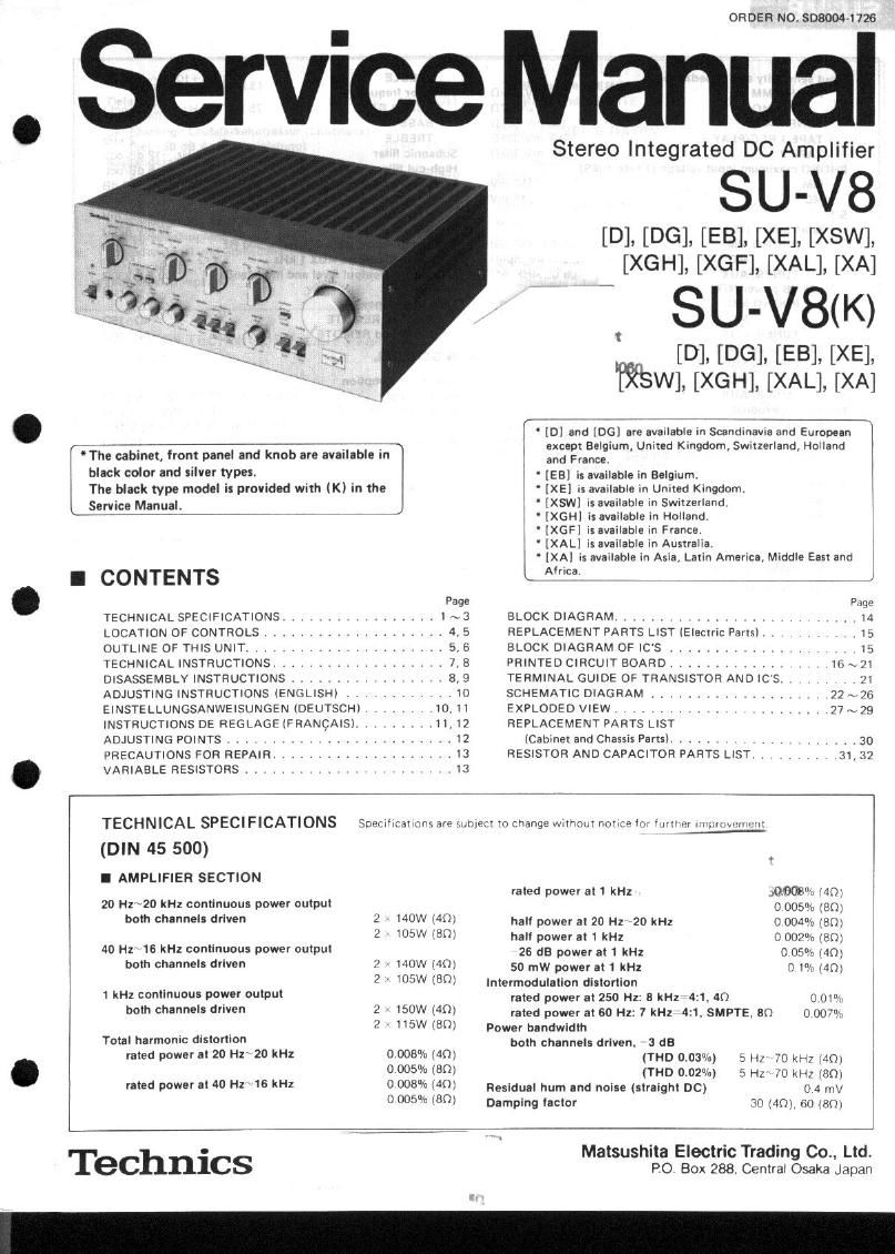
Technics SUV 8 Service Manual

This is the 17 pages manual for Technics SUV 8 Service Manual.
Read or download the pdf for free. If you want to contribute, please mail your pdfs to info@audioservicemanuals.com.

Page: 1 / 17
left right
Technics SUV 8 Service Manual

Extracted text from Technics SUV 8 Service Manual (Ocr-read)


Page 1

ORDER NO. SD8004-1726

ervice Manual

The cabinet, front panel and knob are available in
black color and silver types,
The black type model is provided with (K) in the
Service Manual.

Stereo Integrated DC Amplifier

SU- V8

[D] [D [EB], [XE], [XSW]
[XGH]],[ X[GF] [XAL] ][XA]

SU- V88(K)

[D] [DG], []XE]),
W], [XGH], [XiBL], [XA]

L " [DI and [DG) are available in Scandinavia and European 1
except Belgium, United Kingdom Swrtzerland, Holland
and France. ,
[E3] is available in Belgium. I
" [XE] is available in United Kingdom.
IXSWI is available in Swiuerland.

' [XGHI IS available in Holland,

[XGFI is available m France.

' [XAL] is available in Australia,

[XAI is available in Asia, Latin America, Middle East and

I CONTENTS Am J
Page Page

TECHNICAL S?ECIF|CATIONS, ....... 1\3 BLOCK DIAGRAM ................... . . . l4
LOCATION OF CONTROLS. . . .......... 4, 5 REPLACEMENT PARTS LIST (Electric Parts) . , 15
OUTLINE OF THIS UNIT. ,, 5, 6 BLOCK DIAGRAM OF IC'S ............. .. .. 15
TECHNICAL INSTRUCTIONS. . ............. 7,8 PRINTED CIRCUIT BOARD ............. .I6\ZI

DISASSEMBLY INSTRUCTIONS ................. 8,9 TERMINAL GUIDE OF TRANSISTOR AND ICS . I . .21

ADJUSTING INSTRUCTIONS (ENGLISH) ........... IO SCHEMATIC DIAGRAM ............ .22 ~ 26
EINSTELLUNGSANWEISUNGEN (DEUTSCH) , 10,11 EXPLODED VIEW. , .......... 27N29
INSTRUCTIONS DE REGLAGEIFRANCAISI ...... 1,]? REPLACEMENT PARTS LIST
ADJUSTING POINTS ........ , . , . . . . . . , I2 [Cabinet and Chassis Farts). . ..... 30
PRECAUTIONS FOR REPAIR. ..... . . . . . .13 RESISTOR AND CAPACITOR IARTS LIST. . . .31, 32
. VARIABLE RESISTORS ........... . . . , , 13
TECHNICAL SPECIFICATIONS SDPClIlIdIIOIvS are semen l0 rhanqe wrrhoni norroe Ior 4mm .[nunjvtlr [.rlr
(DIN 45 500) .
I AMPLIFIER SECTION
rated power at 1 kHz 30.3mm, MD]
20 Hr 20 kHz continuous power oulpul 0 005% (80]
bolh channels driven 2 140W 40) hall power al 20 Hz 20 kHz 0 004% ram
2 ' IOSW [80) hall power al 1 kHz 0 002% ram
40 Hz' 16 kHz continuous power oulpul 25 dB power at 1 kHz 0 050' (40)
both channels driven 2 NOW (40) 50 mw power al1 kHz 0 1% 40)
2 ' IOSW I80) lntermodulallon distortion
1 RH! WWW PW" WIP'" rated power at 250 Hz: 8 kHz 4:1, 40 0 on.
both channels (""9" 2 ' 150W [40! rated power al so Hz: 7 kHz 4:1. SMPTE. an o 0070,.
2 SW (ED) Power bandwidth
Total harmonic distortion both channels driven, 3 dB
rated power at 20 Hz' 20 H4: 0 008° n (40) (THD 0,030,, 5 H, 70 kHz [40]
. 0 005% (80) (THD 0.02%) 5 Hz 70 kHz [80l
rated power a! 40 115 WI 0 003%l401 Residual hum and noise (straight DC) 0 4 mV
0 005% (ED) Damping lactor 30 (A0) 60 [8()]

Matsushita Electric Trading Co., Ltd.
PO Box 288. Central Osaka Japan

Technics

Page 2

I ADJUSTING INSTRUCTIONS_ ENGLISH -

0 Setting 00 controls and instruments to be used

1. Operation switch . straight DC 3, Sound volume ....... 0 (minimum)
2. Speaker switch ...... main 4. DC voltmeter (capable to measure 5mV)
Na. Adjustments DC voltmetlr Connections Adjusting Point Adjustment Procedure
' Turn voltage regulator semi-fixed resistor
Voltage VH301 to minimum.
1 regulator 88W" - and VR401 (counter-clockwise direction)
ground Adjust VFMOI to 17,5V
L channel ' Adjust VR30I to obtain a minimum reading,
using the 30mV range on the DC voltmeter
2 Between Heat ((9) and vnam (within: mmv)
ground ' Cut off the jumper wire (J301) if adjustment
is not posible.
- DC Balance
Fl channel ' Adjust VR302 to obtain a minimum reading,
3 VR302 using the SOmV range on the DC voltmeter

Between R652 ((1)) and
ground

L channel Between -
and _ (minus probe)

4 Clamp Voltage

R channel Between -
and - (minus probe)

' Cut off the jumper wire (J302) it adjustment
is not possible.

VR603 (L channel

VR604 (R channel)

- Turn loo semi-fixed resistors VRGOl , 602 to

minimum. (counter-clockwise direction)
' Adjust VR603 (L ch) and VR604 (R ch) to
approx. 1mV alter ten minutes warmup time.

L channel Between -

VR601 (L channel)

5 adjustment using and _(minus probe) forgivflfia" Litgrleifimsgzvjafirfimgo
a DC voltmeter) R channel between - VR602 (Fl channel) time,
and -lminus probe)

0 ICO can be adjusted with oscilloscope and the distortion 2nd Volume control to maximum of this unit.
tflllvnf- 3rd Connect the distortion analyser to the speaker
Instruments 0 5. used terminals and connect the output from the distor-
), Oscillator (20kHZ sine wave) tion analyser to the vertical input of the oscillos-
2. Distortion analyser cope.

3_ Oscilloscope 4th Turn the oscillator attenuater so that the output at
. . the speaker terminal reaches 20V.
1" {Feed mild-'2 Sine wave into the TUNER or AUX 5th Adjust the ice semi-fixed resistors VR601 (left
ermina 5.

channel), VR602 (right channel) for minimum
distortion on the oscilloscope.

I EINSTELLUNGSANWEISUNGEN _-DEUTSCH_

0 Einstallung der zu benutzendcn Regler und Instruments
1. Betriebsschalter. . . . . .Gleichstrom (direkt)
2. Lautsprecherschalter . .Hauptlautsprecher ("main")

3. Lautstarke. ....... "O" (Minimalstellung)
4. Gleichstromvoltmeter. . 5mV Meleereich erforderlich.

Nr Einnellungon Gloiohnromvoltnmervorhindungen Einstnllungspunkto

Einstellunwvoruanu

" Die spannungsregler halbfesteingenollten
Widersténde VR301 aut Minimalstellung
drehen. (Entgegen dam Uhrzeigersinn)

" VR401 aut 17.5V abstimmen.

Spannung-
sregler

Zwischen - und Masse.

VR401

' Durch Benutzung des 30mV-Bereiches
(innerhalb von 110mV) des Gloichstrom-
voltmeters, den regelbaren Widorsland
VRJOI auf minimalon Wart einstellon.

" Wenn eine Einstellung nicht moglich ist,
die Schaltader (J301l abtrennen.

2 L-Kanal

Zwiscnen R651 (0)) und Masse. VH3

Gleichstrom-
balance

' Durch Banutzung des 30mV-Bereiches
(innerhalb von i10mV) des Gleichstrom-
voltmeters, den regolbaren Widerstand
VR302 auf minimalen Wert einstellen.

Wenn eino Einstellung nicht moglich ist,

die Schaltader 302) abtrennen.

R-Kanol.

3 Zwischen R652 (@l und Masse. VH3.

Page 17

22
P 20 I 21_ I 23 24
'Powersouree circuiu _'-'-'-'-"
for [XAL] and [XA]
I Acton o.or
w I
A
' BRN A: nofizo/uwlwv I I
Ana: eon In".
(VOLTAGE ADJUSTER) '
3y: zsov m X
I D
Are my in § A'Il/b ' [XAL] ..... Available in Australia
I
riff. yr (0 r------ - -
" w" X '\ ,6) . '
ACIOI 0.0. B
I Ase-reuse ~ ull'ltcttll I
' LL.
I g3: Ana:
(1 a I :3 T |
4);! A
we VIL A: no . u Ito/sizzmmv
J 3 o [m I Ana: cm
'5' ANN w [XA] . Available in Asia, Latin America,
_ Middle East apd Africa_
are
i c
All: :
I R P :
r6
AC Ila/IIO/IZOIICOV
ICON!
Agaoz' am -
2 A
V m: no
' a... F: no
.1
I
a In [3:]
9" I nu ID
'zmmrmss
E I! ; Lu
_______
v3
=.
'.'. _
Notes:
_ 1. 51: Phone selector switch in phone 1 m" position.
(D phone 1 MCH® phone 1 MMH© phono 2 MM
2. 52: Input selector switch in phone" position.
(I) aux-~® tunerHQ phonoH© tape 1....@ tape 2 h
"u an", 3. 53: Rec selector switch in "pltotto" position. E
® aux~o®tunerfi (,5) phone G) off~® tape dubbing 1 D 2 H
G) tape dubbing 2 >1
4. $4: Muting switch in "0 dB" position.
5. $5: Mode switch in "stone" position.
SfEIEOO-O mono
6. 86: Operation switch in "straight DC" position.
Straight DC via tone
7. 87: High lilter switch in "all" position.
8. so: Subsonic lilter switch In off" position,
9. SO: Loudness switch in "of!" position.
10. 810-1, 10-2: Super bass turnover switch in "75H! HEB/cell" position.
75Hz (12dB/OCII~-'150Hz (12dB/oct) F
11. 811: Speakers selector switch in "min" position.
12. 512: Power switch in on" position.
13. 513: Voltage adjustment switch in 240V" position.

240V0220Vv-v1 10V9120V

14. A Indicates that only parts specified by the manufacturer be sued for safety.

15. C: indicated voltage values are the standard values for the DC electronic circuit tester (high
impedance) with the chasls taken as standard. Therefore, there may exist some errors in the
voltage values. depending on the internal impedance at the DC circuit tester.

16. «mg. Phone signal lines of left channel

17. - Positive (+3) voltage lines.