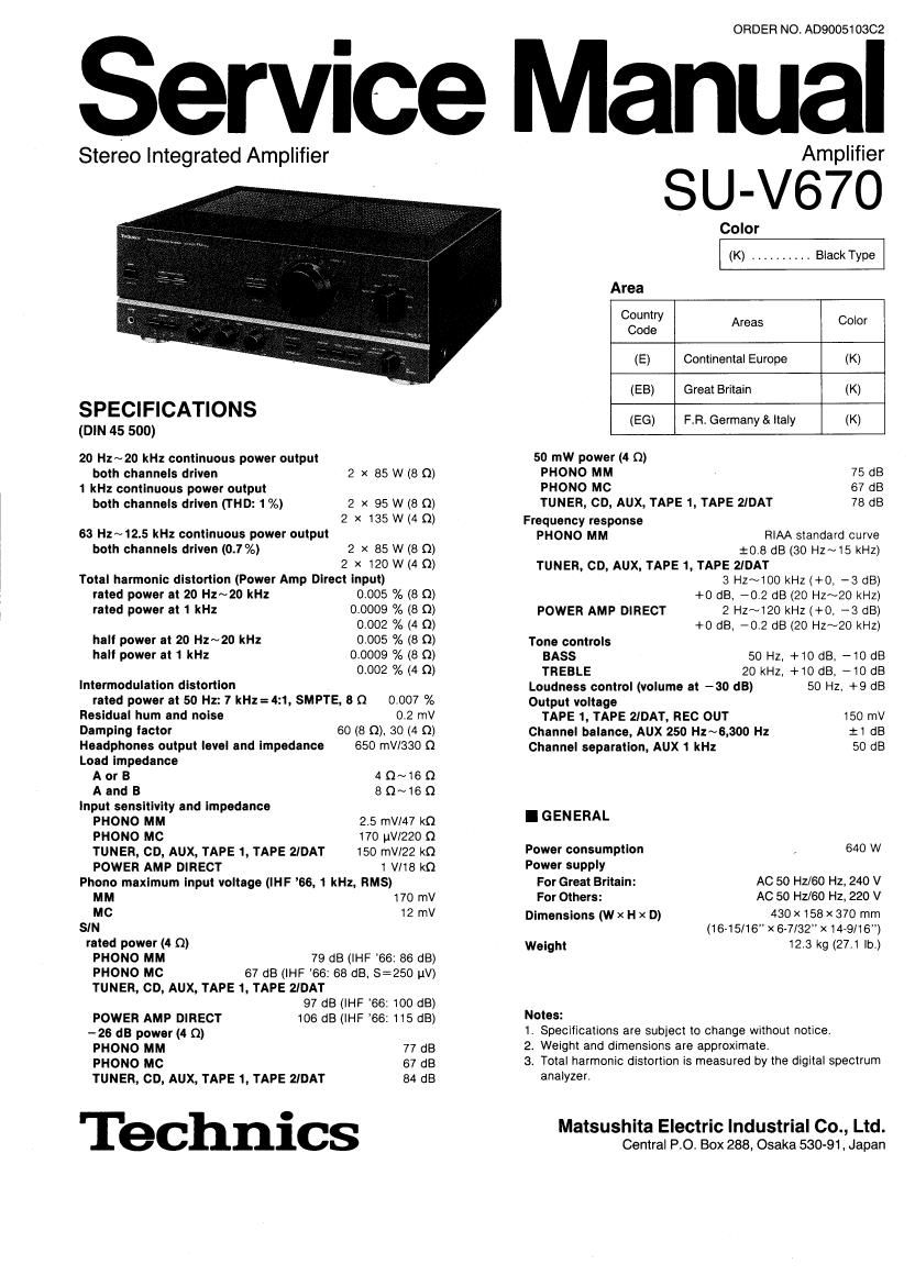
Technics SUV 670 Service Manual

This is the 21 pages manual for Technics SUV 670 Service Manual.
Read or download the pdf for free. If you want to contribute, please mail your pdfs to info@audioservicemanuals.com.

Page: 1 / 21
left right
Technics SUV 670 Service Manual

Extracted text from Technics SUV 670 Service Manual (Ocr-read)


Page 1

I CONTENTS BEFORE REPAIR AND ADJUSTMENT PROTECTION CIRCUITRY ACCESSORY CONNECTIONS LOCATION OF CONTROLS DISASSEMBLY INSTRUCTIONS . . . . . MEASUREMENTS AND ADJUSTMENTS SCHEMATIC DIAGRAM . . . . _ Page 2 2 2 3, 4 5 . 6~9 10 11~13 WIRING CONNECTION DIAGRAM PRINTED CIRCUIT BOARDS TERMINAL GUIDE OF IC'S, TRANSISTORS AND DIODES BLOCK DIAGRAM REPLACEMENT PARTS LIST EXPLODED VIEW Page 14 15~18 18 1 9, 20 . 21 , 22, 25, 26 23, 24 I BEFORE REPAIR AND ADJUSTMENT (1) Turn off the power supply. Using a 10~, 10W resistor, shortcircuit both ends of power suppiy capacitors (C705,C706)in order to discharge the voltage. (2) Before turning on the power switch cf the unit. A. Connect the voltage controller to the primary side. B. Connect the AC ampere meter to the primary side or connect the DC voltage meter to the ":tB" circuit of the secondary side. C. Turn the VR of iCQ (VR451 and VR452) to minimum (counterclockwise). D. Atter setting the output to zero of the voltage contoiler,turn on the power switch of the unit. And increase the output of voltage controller gradually. Then, check carefuily whether the current value ct primary side become more than foilowing vaiue or whether the DC voltage of secondary side is increasing slowly. E. If the value ot current is increasing unusually or the DC voltage is not increasing,lower the output level of voltage contoller immediately. o The current value of the primary side at no signal. (Confirm the power supply voltage of each area and provided voltage of the unit.) I PROTECTION CIRCUITRY The protection circuitry of the amplifier may have operated if either of the following conditions is noticed: e No sound is heard when the power is turned on. e Sound stops during a performance. The function of this circuitry is to prevent circuitry damage if, for example, the positive and negative speaker connection wires are "shorted" , or if speaker systems with an impedance less than the indicated rated impedance of the amplifier are used. If this occurs, foilow the procedure outlined below: 1.Turn off the power. 2.Determine the cause of the problem and correct it. 3.Turn on the power once again. Note: When the protection circuitry functions, the unit will not operate unless the power is first turned off and then on again. I ACCESSORY eAC power supply cord (SFDAC05E03) (S JAI 93) 1 For [E] and [EG] areas. For [EB] area only. -2-

Page 2

I CONNECTIONS "PHONO" terminals to reduce noise. Remove the pins before connecting a turntable and reinsert the pins if the turntable is later disconnected. Never ebnnect a shorting pin to a "REC OUT" terminal or any terminal other than those above. Using the short¥circuit pins (included) Shorting pins are inserted into the Turntable (not included) Tape deck I (not included) Compact disc player (not included) 'Phono input capacitance is about 270 pF for EG area (about I OO pF for other areas). Make connections to each component in the system by using stereo connection cables (not included). "PHONO" terminals "CD" terminals Connect a turntable. (GND) (R) (L) See "Using the short-circuit pins", above. Turntable (not included) (R) (L)(GND) Connect a compact disc player. CO, (R) (L) Compact disc player (not included) LINE OUT (R) (L) Ground wire (not included) "TUNER" terminals "AUX" terminals Connect a tuner. ~r~~ #N~ ~l (R) (U Tuner (not included) OUTPUT ( (L) Connect a component such as a video disc player (audio only con-nectable), etc. -~F'. ,. ::~~~::.:~' :~ Video disc player (not included) ~l (R) (L) LINE OUT (R) (L) -3-