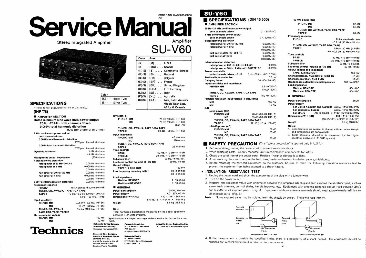
Technics SUV 60 Service Manual

This is the 15 pages manual for Technics SUV 60 Service Manual.
Read or download the pdf for free. If you want to contribute, please mail your pdfs to info@audioservicemanuals.com.

Page: 1 / 15
left right
Technics SUV 60 Service Manual

Extracted text from Technics SUV 60 Service Manual (Ocr-read)


Page 1

Stereo Integrated Amplifier

ORDER NO. HAD8603408C0

Service Manual

Amplifier

SU-V6O

Color Area
(K) [M] ..... U.S.A.
(K) [MC] . . . . Canada
(KHS) [E] ..... Continental Europe
(Kiis) [EH] . . . . Holland
(KliSl [EB] .... Belgium
(KliS) [EF] . . . . France
(KHS) [EK] . . . . United Kingdom
(KliSl [EGA] F.R. Germany
Color (KNS) [Ei] . . . . . Italy
(K) Bi k (KHSI [XL] . . . . Australia
' ' ' 3° Tvpe (K)(Sl [XA] . . .. Asia, Latin America,
SPECIFICATIONS (S) ' ' ' ' Silver Type Middle Near East,
( * Refer to next page, specification of DIN 45 500) Africa 81 Oceania
(IHF 73)
I AMPLIFIER SECTION S/N (IHF, A)
Rated minimum sine wave RMS power output PHONO MM 76 dB (35 dBr IHF _66l
20 Hz~20 kHz both channels driven MC 72 dB (63 362:: :3;
0'00" total harmoggivy'gégggannnel (8 ohms) TUNER, co, AV/AUX, TAPE 1/DA TAPE
TAPEZ BOdB 100 dB, IHF'GG
1 kHz continuous power output In at lm e dance ( >
both channels driven p PHOPNO MM 47 kilohms
0.000% total harmonic distortion M C 220 ohms
90W per channel (8 ohms)
0.005% total harmonic distortion :2::? CD' AVIAUX TAPE DA TAPE 22 '0th
100W per channel (4 ohms) Tone controls
Dynamc headmm 1 1:: (i 22:? BASS 50 Hz. +10 GEN-10 dB
. i ) TREBLE 20 kHz, +10 dB~i10 dB

Headphones output impedance (330 ohms)
Total harmonic distortion
rated power at 20 Hz~20 kHz

rated power at 1 kHz

0.002% (8 ohms)
0,0009% (8 ohms)
0.005% (4 ohms)
000%: (8 ohms)
0,0008% (8 ohms)
0.002% (4 ohms)
0.005% (8 ohms)

halt power at 20 Hz~20 kHz
halt power at 1 kHz

SMPTE inlermodulation distortion
Frequency response

PHONO RIAA standard curve 10.8 dB
TUNER, CD, AVIAUX, TAPE 1/DA TAPE
TAPE2 +0 dB, -0.2 dB (20 Hz~ 20 kHZ)

5 Hz~120 kHz, -3 dB
Input sensitivity
PHOMO MM 0.25 mV (2.5 mV, IHF '66)
MC 17uV(170uV, IHF66)
TUNER, CD, AV/AUX 15 mV (150 mV. IHF '66)

TAPE 1/DA TAPE, TAPE 2
Maximum input voltage
PHONO MM 160 mV
MC 12 mV

Technics

Subsonic illter 20 Hz, *6 dB/oct.

Loudness control (volume aiSO dB) 50 Hz, +9 dB

Output voltage
TAPE 1, 2 REC OUT 150 mV
Low frequency damping lactor 60 (8 ohms)
30 (4 ohms)

Load impedance

MAIN or REMOTE 4~16 ohms
MAIN and REMOTE 8~16 ohms

I GENERAL
380W, 440 VA

Power consumption
Power supply
Dimensions (WXHXD)

AC 120V, 60 Hz

430 X 116 X 340 mm

(16-15/16" X 4-9/16" X 136/16")
Weight 8.5 kg (18.8 lb.)

Note:
Total harmonic distortion is measured by the digital spectrum
analyzer (HP. 3045 system).

Specifications are subject to chnge without notice for further improve-
merit.
u-uusimn some. Company
50 Meadowlnnd Parkway.
Secaucus. New Jersey 07094

Iltlulhltl Eltclvic Trading Cm, Lid:
no. Box 238. Central Osaka Japan

Pnnuonlc Haw-ll, Inc.
91436 Kauhi Sit. Ewa Beach
PI). Box. 174

Honolulu, Hawaii 96608-0774

Pennant: Solos Company,
Dlvilion at lunch": Electric MINI! Eloctric
ot Plum Iloo, Inc. 0' Canada Limited

Ave. 65 De Inisnteril, KM 9.7
Victoria, Industrial Park

5770 Ambler Drive, Mississauglr
Ontario, LW 2T3

Carol-no, Pueno Rico 00630

I SPECIFICATIONS (DIN 45 500)

I AMPLIFIER SECTION
20 Hz~20 kHz continuous power output

both channels driven 2 X 90W (80)
1 kHz continuous power output
both channels driven 2 X 120W (40)

Total harmonic distortion
rated power at 20 Hz~20 kHz
rated power at 1 kHz

0.002% (on)
0.005% (49)
0,0009% (80)
0.002% (80)
0.002% (40)
0.0008% (30)

hali power at 20 Hz~20 kHz
hali power at 1 kHz

lntermodulatlon distortion

rated power at 250 Hz: 8 kHz= 0.005%

rated power at 60 Hz: 7 kHl=4.1, SMPTE, 80 0.005%
Power bandwidth

both channels driven, -3 dB 5 Hz~60 kHz (SQ, 0.03%)
Residual hum and noise 0.8 mV

Damping lactor 30 (40), 60 (80)

Input sensitivity and impedance

PHONO MM 2.5 mV/47kQ
MC 170 {JV/2200
TUNER, CD, AV/AUX, TAPE 1/DA TAPE
TAPE 2 150 mV/22k0
PHONO maximum input voltage (1 kHz, RMS)
MM 160 mV
MC 12 mV
SIN
rated power (40)
PHONO MM 78 dB (86 dB, IHF, A)
MC 65 dB (68 dB, IHF, A)
TUNER, CD, AV/AUX, TAPE 1/DA TAPE
TAPE2 92 dB (IHF, A: 100dB)
~26 dB power (an)
PHONO MM 69 dB
MC 65 dB
TUNER, CD, AV/AUX, TAPE 1/DA TAPE
TAPE 2 70 dB

50 mw power (40)

PHONO MM 62 dB
MC 61 dB
TUNER, CD, AV/AUX, TAPE 1/DA TAPE
TAPE 2 53 dB
Frequency response
PHONO RIAA standard curve

i053 dB (30 Hz~15 kHz)
TUNER, CD, AV/AUX, TAPE 1/DA TAPE
TAPE 2 5 Hz~120 kHz (-3 dB)
+0, *0,2 dB (20 Hz~20 kHz)
Tone controls
BASS 50 Hz, +10dB~-10 dB

TREBLE 20 kHz, +10 dB~-10dB
Subsonic filter 20 Hz, -6 dB/oct.
Loudness control (volume at 730 dB) 50 Hz, +9 dE
Output voltage and impedance

TAPE, 1,2 REC OUT 150 mV
Channel balance, AUX 250 Hz~6,300 H1 :1 dB
Channel separation, AUX 1 kHz 50 dB
Headphones output level and impedance 600 mV/33OQ
Load impedance

MAIN or REMOTE 4Q~1 60

MAIN and REMOTE 80~160
I GENERAL
Power consumption 560W

Power supply
For United Kingdom and Australia AC 50 Hz/60 Hz. 240V
For continental Europe AC 50 Hz/Go Hz, 220V
For others AC 50 H2/80 Hz, 110V/127V/220V/240V
Dimensions (WXHXD) 430 X 116 X 340 mm
(16-15/16" X 4-9/16" >< 13-6/16)
Weight 8.5 kg (18.8 lb.)

Notes:

1. Specifications are sub)ect to change withoutnotice, Weight
and dimensions are approximate.

2. Total harmonic distortion is measured by the digital
spectrum analyzer (HP. 3045 system).

Before servicing, unplug the power cord to prevent an electric shock.

When replacing parts, use only manufacturer's recommended components for safety,

Check the condition of the power cord. Replace if wear or damage is evident.

After servicing, be sure to restore the lead dress, insulation barriers, insulation papers, shields, etc.

I SAFETY PRECAUTION (This safety precaution is applied only in U.S.A.)
1,
2,
3,
4.
5.

Before returning the serviced equipment to the customer, be sure to make the following insulation resistance test to
prevent the customer from being exposed to a shock hazard.

INSULATION RESISTANCE TEST

1. Unplug the power cord and short the two prongs of the plug with a jumper wire,

2. Turn on the power switch.

3, Measure the resistance value with ohmmeter between the jumpered AC plug and each exposed metal cabinet part, such as
screwheads antenna, control shafts, handle brackets, etc. Equipment with antenna terminals should read between 3M9
and 5.2M!) to all exposed parts. (Fig. A) Equipment without antenna terminals should read approximately infinity to

all exposed parts. (Fig. B)

Note: Some exposed parts may be isolated from the Chassis by design, These will read infinity,

Antenna
terminal \

Exposed
metal
part

Ohmmeter
(IU-A)

Resustance = 3MQ~S2 M9

Exposed D
metal
part
Ohmmeter
(Fig. 3)

Resistance : Approx 00

4, If the measurement is outside the specified limits, there is a possibility of a shock hazard, The equipment should be
repaired and rechecked before it is returned to the customer.

-2_

Page 2

I CONTENTS

Page

SAFETY PRECAUTION ...........................
LOCATION OF CONTROLS . . . . . . . . . . . .
PROTECTIONCIRCUITRY .........
BEFORE REPAIR AND ADJUSTMENT . .
DISASSEMBLY INSTRUCTIONS ......
MEASUREMENTS AND ADJUSTMENTS . . t . . .
BLOCK DIAGRAM ......................... 7

I LOCATION OF CONTROLS

Balance control--

(treble)
Tone controls-E
(bass)

Power switch

2 PRINTED CIRCUIT BOARDS . . . . . ........ . . .
CIRCUIT BOARDS AND WIRING

3

4 CONNECTION DIAGRAM ........
4 SCHEMATIC DIAGRAM .............. .
6

6

8

REPLACEMENT PARTS LIST ......
EXPLODED VIEW ......... . .

(Volta a control) . .
9 l-Amplifier operation indicator
i'_ (current drive

Subsonic filter (I. off, A ZOHz)

Loudness switch ( 1 off, - on)

CD direct ( I. off, - on)

Volume control

O

(9

Tone control

(1 direct, - on)-E

Headphones jack-© Up DD

(main)-
Speaker selector-E
( 1 off, - on]

Recording-mode selector ---
(tape 1 >2, tape 2 b 1, AV/aux, CD, tuner, phono)

Tape l/DA tape (Playback)
(Rec out)
(Playback)
Tpae 2
{Mac out)

Tape 2

l-Tape monitor selectors
-Tape l/DA tape

Speaker impedance selector

(8~16SZ/16§2<,::>4~6S2/8$2)

AC inlet

(Total 200W MAX.)

ram

I=I|n

-9 em

9-6)
Cu
(90
@@

g llillll mail]
| .
ll
ll

I :3

~CD©

69
@m

GroundJ
Tuner

iii

(For [XA) area only)

AV/Aux-

L

Main speaker terminal

Remote speaker terminal

O3_

Page
. 9~14

15 ~16
17~21

- - 22 ~23
-24, 25

Phone selector ( 1 MM, .- MC)

[-Recording selector

indicators
V |
LInput selector
indicators
l- (phono)
(remote) (tuner)
- Input selectors
(CD
(AV/aux l-l

Switched (50W MAX.) AC l
. I- out ets
Unswrtched [For M, MC, XA

areas]

LVoltege selector (on the bottom board)
(127V 4-» 110V H 220V<->24OV)

0 The power supply for this unit varies depending upon the areas. Also, the parts used for power supply are different.
So, refer to the circuit diagram and replacement parts list.

' [M] [MC] area is provided with AC outlets.

120V (60Hz) for USA.

* [XA] area is provided with voltage selector and AC outiets.

* 240V (BO/GOHz) for Australia and United Kingdom.

* 220V (50/60Hz) for Continental Europe.

* 127V/110V/220V/240V (50/60Hz) for other [XA] area.

* Phono input capacitance is about lSOpF.

Suggestions
Notes:

0To record sounds from a compact disc. press the input
selector marked CD",

The compact-disc-direct switch is for listening only; it
cannot be used to select the compact disc as a recording
source.

Olf noise is very annoying while listening to an FM or AM
broadcast, switch OFF the video disc player, compact-disc
player and turntable.

OSwitch OFF the video disc player power if noise is
excessive while listening to an audio tape, compact disc or
regular phone disc.

I PROTECTION CIRCUITRY

The protection circuitry may have operated if either of the following conditions is noticed:
0 No sound is heard when the power is switched ON.
0 Sound stops during a performance.
The function of this circuitry is to prevent circuitry damage if, for example, the positive and negative speaker connection wires
are "shorted , or if speaker systems with an impedance less than the indicated rated impedance of this unit are used.
if this occurs, follow the procedure outlined below:
1. Switch OFF the power.
2. Determine the cause of the problem and correct it.
3. Switch ON the power once again:
Note:
When the protection circuitry functions, the unit wiil not operate unless the power is first switched OFF and then ON again.

I BEFORE REPAIR AND ADJUSTMENT

(1) Turn off the power supply. Using a 109, SW resistor, shortcircuit both ends of power supply capacitors (C503, C504,
68001.1F) in order to discharge the voltage.
(2) Before turning on the power switch of the set . . .
A. Connect the voltage controller to the primary side.
B. Connect the AC ampere meter to the primary side or connect the DC voltage meter to the i B circuit of the
secondaw side.
C. Turn the VFl of ICC (VR401 and VR402) to minimum (counterclockwise),
D. After setting the output to zero of the voltage contoller, turn on the power switch of the set.
And increase the output of voltage controller gradually.
Then, check carefully whether the current value of primary side become more than followings value or whether
the DC voltage of secondary side is increasing slowly.
E. If the value of current is increasing unusually or the DC voltage is not increasing, lower the output level of voltage
contoller immediately.
. Check the transistors of voltage amplifier and current amplifier ICSO1.
. After repairing, adjust the ICC,
0 The current value of the primary side at no signal. (Confirm the power supply voltage of each area and provided
voltage of the set.)

011

AC1 10V
280 ~ 560mA

AC'IZOV
260 ~ SZOmA

AC127V
260 ~ 520mA

ACZZOV
140 ~ ZBOmA

AC240V
l 30 N ZGOmA

Power supply voltage
50/ 60Hz

Consumed current