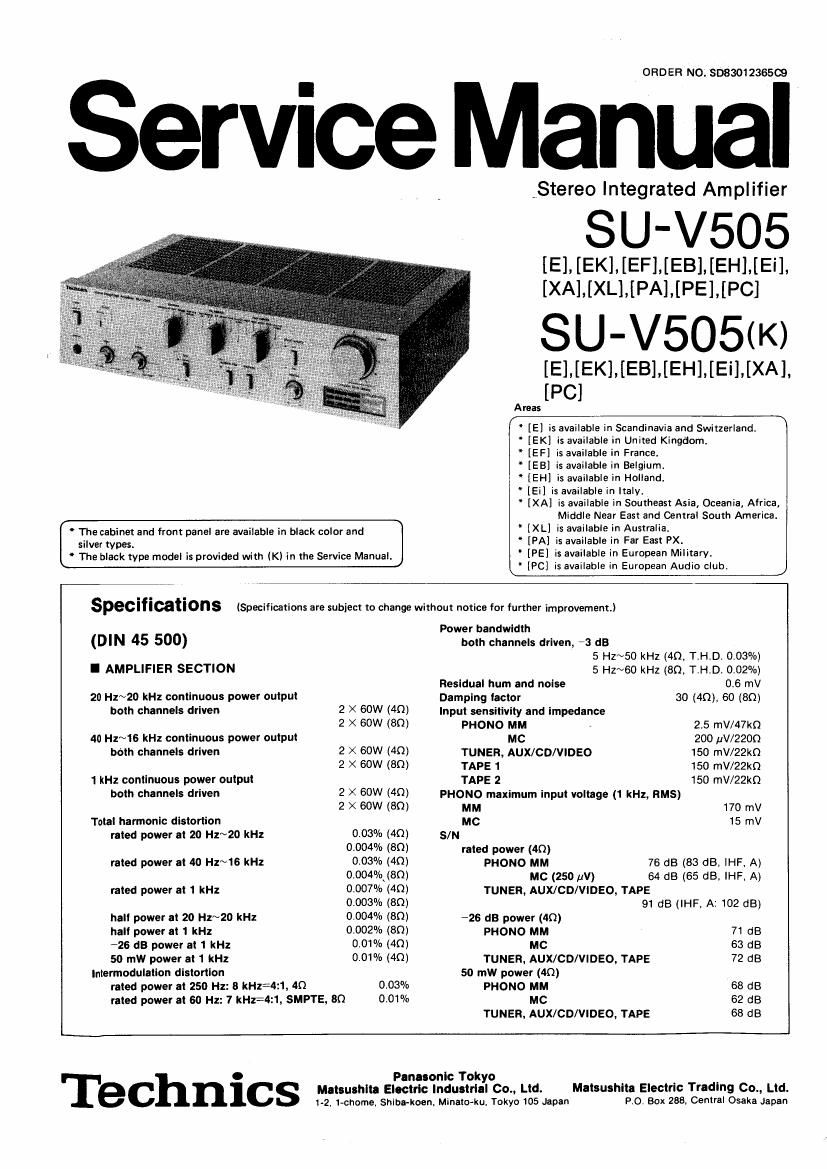
Technics SUV 505 K Service Manual

This is the 29 pages manual for Technics SUV 505 K Service Manual.
Read or download the pdf for free. If you want to contribute, please mail your pdfs to info@audioservicemanuals.com.

Page: 1 / 29
left right
Technics SUV 505 K Service Manual

Extracted text from Technics SUV 505 K Service Manual (Ocr-read)


Page 1

ORDER NO. 808301 2365(3

Service Manual

,Stereo Integrated Amplifier

SU-V505

[E]. [EK].[EF].[EBI. [EH].[Ei].
[XA],[XL].[PA].[PE].[PC]

SU- V5O5(K)

[E] [EK]. [EB] [EH] [Ei] [XA]
[PC]

Areas

" [E] is available in Scandinavia and Switzerland.

' [EK] is available in United Kingdom.

" [EF] is available in France.

[EB] is available in Belgium.

" [EH] is available in Holland.

[Ei] is available in Italy.

[XA] is available in Southeast Asia, Oceania, Africa,
Middle Near East and Central South America.

W

The cabinet and front panel are available in black color and
silver types.

[XL] is available in Australia.
" [PA] is available in Far East PX.
' [PE] is available in European Military,

\ The black type model is provided with [Kl in the Service Manual.

[PC] is available in European Audio club. J

. . .
SpeCIflcatlons (Specifications are subject to change without notice for further improvement.)

Power bandwidth
both channels driven, *3 dB
5 HZ~50 kHz (40, T.H.D. 0.03%)
5 Hz~60 kHz (80. T.H.D. 0.02%)
0.6 mV
30 (4Q), 60 (8Q)

(DIN 45 500)

l AMPLIFIER SECTION
Residual hum and noise

20 H1~20 ka continuous power output Damping lactor

both channels driven 2 X 60W (40) Input sensitivity and Impedance
2 X 60W (80) PHONO MM 25 I'nV/47kQ
40 Hz~16 kHz continuous power output MC 200 uV/ZZOQ
bélh channels driven 2 X 60W (40) TUNER, AUX/CD/VIDEO 150 II'lV/22kQ
2 X 60W (80) TAPE 1 150 mV/22kQ
1 kHz continuous power output TAPE 2 150 mV/22kn
both channels driven 2 X 50W (40) PHONO maximum input voltage (1 kHz, RM5)
2 X 60W (50) MM 170 mV
Total harmonic distortion MC 15 mv
rated power at 20 Hz~20 kHz 0.03% (40) SIN
0.004% (30) rated power (40)
rated power at 40 Hz~16 kHz 003% [40) PHONO MM 78 dB (83 dB, IHF, A)
0.004%.(80) MC (250 uV) 64 dB (65 dB, IHF. A)
rated power at 1 kHz 0.007% (40) TUNER, AUX/CD/VIDEO, TAPE
0.003% (80) 91 dB (IHF, A: 102 dB)
hall power at 20 Hz~20 kHz 0.004% (80) -26 dB power (40)

hall power at 1 kHz 0.002% (80) PHONO MM 71 dB

726 dB power at 1 kHz 0.01% (40) MC 63 dB

50 mW power at 1 kHz 0.01% (40) TUNER, AUX/CD/VIDEO, TAPE 72 dB
Interrnodulation distortion 50 mw power (40)

rated power at 250 Hz: 8 kHz34z1, 40 0.03% PHONO MM 68 dB

rated power at 60 Hz: 7 kHz=4:1, SMPTE, 80 0.01% MC 62 dB

TUNER. AUX/CD/VIDEO, TAPE 68 dB

Pun-sonic Tokyo
Matsuthlu Electric Industrial Co., Ltd.
I-2. 1-chome, Shiba-koen. MinatoAku, Tokyo 105 Japan

Matsushita Electric Trading 00., Ltd.
P.O. Box 288. Central Osaka Japan

Technic

Page 2

Frequency response
PHONO RIAA standard curve
$0.8 dB (30 Hz~15 kHz)
TUNER, AUX/CD/VIDEO, TAPE 5 Hz~140 kHz (-3 US)
+0 d8, *02 dB (20 Hz~20 kHz)

Tone controls
BASS 50 Hz, +10 dB~ 10 dB

TREBLE 20 kHz, +10 dB~ -10 dB
Subsonic filter 30 Hz, *6 dB/oct.
Loudness control (volume at -30 dB) 50 Hz, +9 dB
Output voltage and impedance

REC OUT 150 mV
Channel balance, AUX/CD/VIDEO 250 H1N6,300 Hz i1 dB
Channel separalion, AUX/CD/VIDEO 1 kHz 63 dB

Headphones output level and impedance 520 mV/aaoo
Load Impedance
MAIN or REMOTE

MAIN and REMOTE

4Q~160
80~160

. GENERAL

Power consumption 370W
Power supply

For continental Europe iExcept for United Kingdom)

AC 50 Hz/GO Hz, 220V

For Australia AC 50 Hz/6O Hz. 240V

For others AC 50 Hz/60 Hz. 110V/120V/220V/240V

Dimensions (WXHXD) 430 X 109 X 290 mm

(16-15/16" X 4-9/32"><11»13/32)

7.6 kg

(16.8 lb.)

Weight

Note:
Total harmonic distortion IS measured by the digital spectrum
analyzer (HP. 3045 system),

I CONTENTS

SAFETY PRECAUTION . . . .
LOCATION OF CONTROLS . . . . .
PROTECTION CIRCUITRV .........
BEFORE REPAIR AND ADJUSTMENT . .
MEASUREMENTS AND ADJUSTMENTS .
TECHNICAL INFORMATION ........
OPERATION OF lcu CONTROLLER . . .

BLOCKDIAGRAM ...............

I SAFETY PRECAUTION

Before servicing (such as replacement of components), unplug the power supply cord to prevent an electric shock.
Use only manufacturers recommended components for safety, Check condition of power cord and replace if wear or

I.
2.

3.

o
1
2
3

damage is evident.


Page

CIRCUIT BOARDS AND WIRING
CONNECTION DIAGRAM ......... . . . . 17,18
PRINTED CIRCUIT BOARDS . . . . . . . . 19" 22
SCHEMATIC DIAGRAM .......... 23 ~ 28

FUNCTION OF TERMINAL (ICO CONTROLLER IC702) ..... 28
RESISTORS & CAPACITORS ........... . . . .

REPLACEMENT PARTS LIST
EXPLODED VIEWS .......


After servicing, be sure to restore the following to the condition in which they were originally installed

(ll the lead dress and

(2) insulation barriers, insulation papers, shields and the like
. Before returning a serviced apparatus to a customer, make the following insulation resistance test to prevent a customer

from being exposed to a shock hazard.

Insulation resistance test (See figure below.)

. Unplug the power supply cord and connect a jumper wire between the two prongs on the plug.
. Turn on the power switch of the apparatus.
. Measure the resistance value (with an ohmmeter) between the jumpered AC plug and each exposed metalic cabinet part on

the apparatus, such as screwheads, antenna, control shafts, handle brackets, etc.
The reading should be as shown in figure below. In case a measurement is outside of the limits specified, there
is a possibility of a shock hazard, and the apparatus should be repaired and rechecked before it is returned to a customer.

Tuner, Receiver etc.

Antenna
terminal \

Exposed
metal
part

Ohmmeter

3MQ

Turntable, Amplifier etc.

Exposed
metal
pan

Ohmmeter

R = nearly m

where, H: resistance value

i
l.
é

Page 6

* Precautions for Fitting the Push-buttons

1, When replacing push-button, remove the
front panel beforehand.

2. it should be fitted onto the switch with
the spherical side down as in Fig. 8.

0 How to remove and fit the remote switch

. How to remove -
Pushing the remote
switch , shift it up as
in Fig, 9,

a

Push-button

Pushswitch

[Fig. 8]

. How to fit -

(1) Shift the switch contact inside.

(2) Turn the remote switch (selector knob) counterclock-
wise.

(3) Let the remote switch claw engage with the switch. and
shift the remote switch down while pushing it in.

I MEASUREMENTS AND ADJUSTMENTS

1. Clock Adjustment (after replacing the microcomputer)

law

front panel.")

Computer drive LED case

Switch
00 nlact

[Fig. 10]

* How to remove the computer drive LED case
1. Remove the cabinet and front panel. (Refer to "How to remove the

2. Release the 3 claws of computer drive LED case (Fig. 11) to remove
the computer drive LED case.
3. When replacing the computer drive LED indicators, unsolder the
LED's of D712 ~ 718 and remove them from the printed circuit

board along with the computer drive LED case because the case and

[Fig. 11]

(1) Turn off the power supply.
(2) Adjust VR701 so that the time until the relay turns ON is 5 ~ 7 sec. after power ON.

* The time elongates with VR701 turned counterclockwise (in the direction of A). (Frequency decreases.)
The time shortens with VR701 turned clockwise (in the direction of B)_ (Frequency increases)

4i

LED's are set up into an assembly.

(Note) Clock frequency of 400 kHz is obtained at . In the case of an ordinary frequency counter and oscillo»
scope, the frequency cannot be correctly measured because of the probe capacity. 80, it is recommended to

2. Idling (lco) Adjustment (after reparing the main amp.)

employ the above-mentioned method during servicing.

(1) After the repair,set the sound volume to minimum before turning on the power switch, and connect nothing

(2)
(3)

(4)

(5)

or

to the speaker terminals.

Completely turn lCQ control (VR301, 302) counter-clockwise.

increase the voltage applied to the amplifier gradually
from 0V by means of a power supply voltage controller,
and make sure of the value in the Figure on page 4 before
starting the adjustments
Connect the DC electronic voltmeter to (+) and
(-) [left channel] or (H and l--l
[right channel].
When 5 or 15 seconds have lapsed after computer drive
monitor "auto" lights up, adjust VR301 [left channel]
or VR302 lright channel] to 2mV.
In this set, ICQ is controlled by microcomputer, and lot]
a little more than the normal level is applied by "PREe
HEAT" for about 15 sec. after power ON. After that, the
output level and transistor temperature are detected by
"AUTO", thereby automatically controlling lCO.

ICO
(bias)

Much Ice is applied by
preheat function

0 l 15
Relay 0N 99°-

5 ~ 15 sec
Bias preheat »

Power ON

19
"II".

Bias auto

Page 9

a Computer drive system

Knowing the thermal and signal characteristics of the
power transistors, a system can be designed to calculate
the instantaneous temperature changes and adjust for
the optimum idling current. Information regarding the
transistor ambient temperature and the input music signal
is obtained through sensors and fed to a computer. The
computer calculates the optimum idle current and main-
tains it at a constant level by varying the bias voltage.
Figure 15 illustrates the relationship of the output signal
and the idling current, Figure 17 is a block diagram of the

computer drive" system.

Generally, it takes several minutes for the power transistors
to reach the temperature of stable operation after the
power is turned on. To ensure stable and optimum per-
formance quickly, the microcomputer forces a large
amount of idling current through the power transistors
for a short time. This rapidly "preheats" the transistors
and the heat sink. Figure 16 illustrates the stable operation
level for the convertional and new computer drive system.

Output signal

DISOTW" In conventional cirCUit,

Ice varies due to signal.
(high distortion)


l
l
' Due to computer drive, lco does
: not vary (causing no distortion)

--i--l-

->t

Output vs idling current

[Fig 15]

Operation by ore-heat i ng

Ico circuit of this unit.

Main amplifier circuit
Computer drive

Main amp

input
0 Voltage

amplifier

Bias circuits
Synchronous
bias Circuit

New class A power amp. circuit


Stable operation

Convertional amplifier

Power is on

\

Computer control
circuit

I Fig. 16]
r 7| fifi Speaker
|
I
|
|
/ : To speaker
I
l
i
l
|

T
l
I
|
|
|
: may drive
I
I
l
|
I
l
l
l

A
I
DC offset
detection
V

Optimum
bias
calculation

-4 Protection |___ | _J .
-L circuit J u i Muting

Micro computer

|
i
i
|
I
I
I
integrator l i
| I
Thermal sensor Signal sensor : 0"de '
(temp. change (signal revel I detection :
detection) detection) l E l
l I I
l | |
l I
t i l
| | I
i _ i l
'- _ _ r- - - - -i

I
i

L _____ J

[Fig. 17]

%-

2. Description of Speaker Impedance Detection Circuit

This circuit serves to detect the impedance of speaker connected to the speaker terminals and to change the
secondary tap voltage of power transformer according to the speaker impedance. It consists of a voltage comparing
circuit, reset circuit, detection signal generating circuit, and speaker select relay drive circuit.

1) Reset circuit and detection signal generating circuit
The reset switch of speaker select switch is shortrcircuited only when the switch is shifted, With the speaker select
switch shifted, the reset switch is short-circuited, then 0601 of reset circuit turns ON. When 0601 turns ON,
positive voltage as in Fig. 18A is generated at the collector of 0601, causing 0602 to turn ON.
When 0602 turns ON, 0321 turns OFF, and so does RLVBOl.

Also, when 0321 turns OFF, the collector potential of 0321 becomes positive, causing 0605 to turn OFF.
Then RLY601 also turns OFF (high volt tap).

When the reset switch is open, a voltage as in Fig. 18-8 is /5"""'"°""'° °' "' m"
applied to the base of 0604 due to the charge and discharge

of C601.

With 0604 turned ON, a voltage as in Fig. 187C is generated

at the collector of 0604. The voltage causes 0602 to turn A _ K Cam, Wm B, 060,
ON.

When 0602 turns ON, RLY301 turns OFF and so does

RLY601 (high volttap). That is, both RLY301 and FlLY601 E L Wm WM 060, m
are OFF during shortecircuit of reset switch and for 0.55ec.

more after opening the switch, 1

Also, when power switch is turned ON, C604 is charged

with voltage, then the base voltage of 0601 becomes '1

0V and 0601 turns ON. Then both RLY301 and RLY601 \

Collector voliaga of 0604

turn OFF, and the speaker impedance detecting circuit
operate. About 0.5sec. after power switch ON, C604 is
discharged and 0601 turns OFF.

rd . 0.5 sec,

Length at time when RLYaoI and
RLVSDI are OFF

[Fig. 18]

2) Voltage comparing circuit
lC301 is a voltage comparing circuit. With RLY301 turned OFF, the speaker is connected to the voltage com-
paring circuit. (Fig. 19) The reference voltage is applied to minus terminals ((1), (Q) of |C301.

Also, plus terminals (3, (5) of |C301 are subject to change according to the impedance of the speaker con
nected to the set.

The adjustment has been made with VR303 and VR304

so that the output voltage of lC301 is CV with 6.59

speaker connected. If the impedance of the speaker cone swan-EL
nected is 49, the output voltage of |C301 becomes nega- {
tiye, causing 0605 to turn ON.

Then RLY601 also turns ON (low volt tap).

If the speaker impedance is 80, the output voltage of
|C301 becomes positive, then 0605 turns OFF and
R LY601 also turns OFF (high volt tap).

Reieunce
4 an voltage

-HB,4V

OUTPUT

/
SPEAKER I \{BNSQ I I g
3) Voltage comparing circuit and reset circuit l mm... L ~ 6:) U?
The operation amplifier of voltage comparing circuit has ""m
a nature to hold the impedance 80, or 49 once detected.
So, if a speaker with different impedance is connected, it is [Fig. 19]

necessary to turn OFF the power supply or shift the
speaker select switch before operating the reset circuit.

rows.