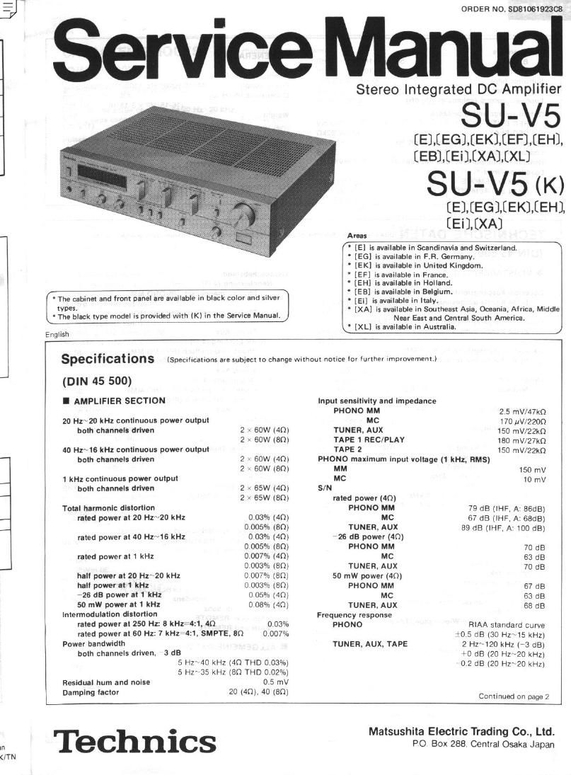
Technics SUV 5 Service Manual

This is the 8 pages manual for Technics SUV 5 Service Manual.
Read or download the pdf for free. If you want to contribute, please mail your pdfs to info@audioservicemanuals.com.

Page: 1 / 8
left right
Technics SUV 5 Service Manual

Extracted text from Technics SUV 5 Service Manual (Ocr-read)


Page 1

TN

ORDER NO. SDB1061923$

Service Manual

° The cabinet and front panel are available in black color and silver

types.
' The black type model is provided with (K) in the Service Manual.

English

Stereo Integrated DC Amplifier

SU-V5

[ELEEGMEKMEFMEH],
[EBMEilEXAMXL]

SU-V5 (K)

[EMEGMEKMEHl
[EilEXA]

' [E] is available in Scandinavia and Switzerland, N

' [E6] is available in FR. Germany.

' [EK] is available in United Kingdom.

' [EF] is available in France.

' [EH] is available in Holland.

' [EB] is available in Belgium.

' [Ei] is available in Italy.

' [XA] is available in Southeast Asia, Oceania, Airica, Middle
Near East and Cantral South America,

' [XL] is available in Australia. J


specltlca Ions (Specifications are subject to change Without notice (or turther Improvementi

(DIN 45 500)
I AMPLIFIER SECTION

20 Hz~20 kHz continuous power output

both channels driven 2 ( 60W (40)
2 . 60W (80)
40 Hx~16 kHz contlnuous power output
both channels driven 2 - 60W (40)
2 - 60W (80)
1 kHz continuous power output
both channels driven 2 - 65W (40)
2 - 65W18m
Total harmonic distortion
rated power at 20 Hz~20 kHz 0 03% (4m
0.005% (am
rated power at 40 Hzmis RM: 0.03% (40)
0 005% (80)
rated power at 1 kHz 0.007% 140)
0.003% (80)
halt power at 20 "1.20 kHz 0 007% (80)
halt power at 1 kHz 0 003» (an)
#26 dB power It 1 kHz 0 05% (40)
50 mW power at 1 kHz 0 08% (4Q)

Intermodulatlon distortion
rated power at 250 Hz: 8 kHz-45. 40 0.03%
rated power at 60 Hz: 7 kH1:4:1, SMPTE, en 0 007%
Power bandwidth
both channels driven. 3 dB
5 HZ 40 kHz (40 THD 0.03%)
5 Hz~35 kHz (80 THD 0.02%)
Residual hunt and noise 0.5 mV
Damping iactor 20 (40). 40 (80)

Input sensitivity and impedance

PHONO MM 2.5 mV/47k0

MC 170 uV/ZZOQ
TUNER, AUX 150 mV/22k0
TAPE 1 REC/PLAY 180 mV/27kn
TAPE 2 150 mV/22k0

PHONO maximum Input voltage (1 kHz, RMS)

MM 150 rnV
MC 10 mV

rated power (40)
PHONO MM 79 dB (IHF. A' BGdB)
MC 67 dB (IHF. A: 68:18)

TUNER. AUX 89 dB (IHF. A: 100 dB)
~26 63 power (40)
PHONO MM 70 dB
MC 63 dB
TUNER, AUX 70 dB
50 mW power (40)
PHONO MM 67 dB
MC 63 dB
TUNER, AUX 68 dB
Frequency response
PHONO RIAA standard curve

+0.5 dB (30 Hzs15 kHz)
2 H2 120 kHz (' 3 (18)
+0 dB 120 HZ20 kHl]
0 2 dB (20 Hz~20 kHz)

TUNER, AUX, TAPE

Continued on page 2

Technics

Matsushita Electric Trading Co., Ltd.
PO Box 288. Central Osaka Japan

Page 2

I BEFORE REPAIR AND ADJUSTMENT

Turn off the power supply and short-circuit both ends of power supply condensers (C601,C602,8200uF) at

resistance iabout 109, SW) in order to discharge the charged voltage. Avoid short-circuit with a screwdriver or the like,
otherwise the transistors or diodes may break down.
Before turning on the power supply after completion of repair, slowly apply the primary voltage by using a voltage
regulator to make sure that the current consumed is free of abnormality. The current consumed at 60H2/50Hz in no-
signal mode is shown below with respect to supply voltage 110V/120V/220V/240Vt

PM apply voltage Ac 110V AC 120V Ac 220V AC 240V

50Hz 260 ~ SZOmA 250 ~ SOOmA 140 ~ 270mA 130 ~ ZSOmA
Current consumed

mHz 250 ~ 500mA 240 ~ 480mA 130 ~ ZSOmA 120 ~ 240mA

I ADJUSTMENT POINTS

I_-'---1 Lch loud Rch loud

\

Test points

:%

Z3_°'_<1£322_J

imp anaem- lmD director

l

I 6.5911/2W) 6.59 i1/2wl
|
|
l
|

523
oooo

MAIN

REMOTE

MAIN

REMOTE


Fig. 18
(Abb. 18)
FL peak power mover P C B
x 1 meter range x 0.01 meter range
(89, 2V output) (89, 2V output)
J G
left I' ' I] l] l] I] W
20 50 IOO a:
right [1 l] [I [I (8 l

FL peak power meter;
Fig. 19 (Abb. 19)

l.