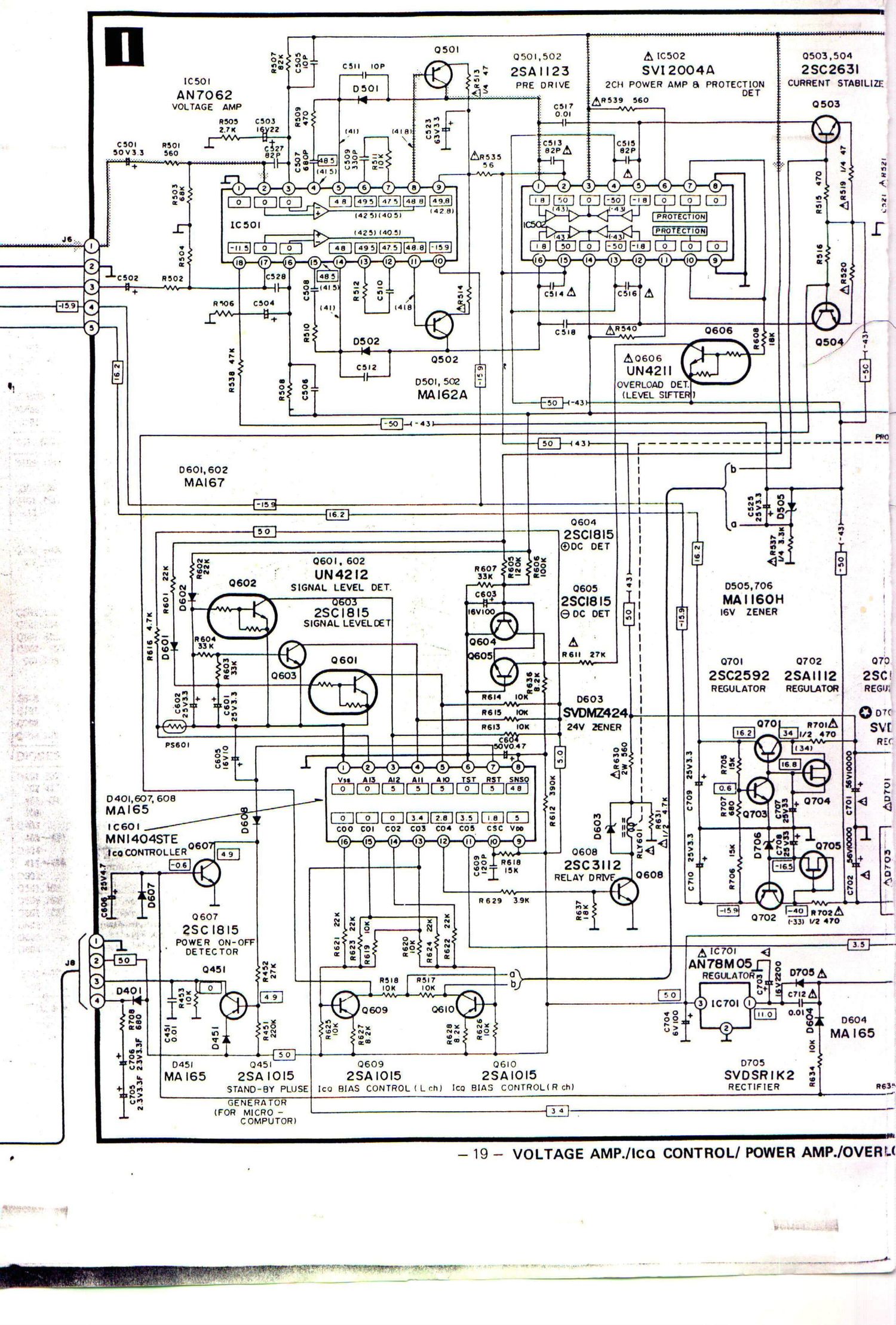
Technics SUV 4 X Schematics

This is the 2 pages manual for Technics SUV 4 X Schematics.
Read or download the pdf for free. If you want to contribute, please mail your pdfs to info@audioservicemanuals.com.

Page: 1 / 2
left right
Technics SUV 4 X Schematics

Extracted text from Technics SUV 4 X Schematics (Ocr-read)


Page 2

in!"

20 21 22 y ' 23 24
SPEAKER SELECT CIRCUIT I SCH EMATIC DIAGRAM

(This schematic diagram may be modified at any time with the
development of new technology).

. The part No. of transistors, 1C and diodes mentioned in the


schematic diagram stand for production part No. Regarding A
R For E R the part No. with 0 mark, the production part No. are
A lggfggggn, Germany only different from the replacement part No. Therefore, when
.. .3523 5 ll -2 placing an order for replacement parts, please use the part
' i" '0 . e No. in the replacement parts list.
2 " ~ I ' l. S1~86 : Input selector switch in "phono"
.3. : 1 position.
f l MAIN Si: phono, 82: tuner, 53: CD,
3 1 S4: video/aux, $5: tape 1/DA
3:?- I J tape, 36: tape 2
-+ : JR Ch 2. S7 : Recording selector switch in "off"
33+ I position. B
3" I SPEAKERS 3. $8 : Muting switch in "OdB" position.
N } (OdB ~ -20dB)
3 L502 1 4. 89-1 : Loudness switch in off" position.
:1 -- LC" Film-om
Rm : _l 5. 89-20. Phono selector switch in MM
I position.
A : REMOTE ~ ( I. MM, _. MC)
I J 6. 510-1 : Subsonic filter switch in "off"
i l R ch position.
I : i i I. off, - on)
I 7. 810-2 : Tone switch in defeat" position.
.J l ( I, defeat, a. on)
spun. : 8. 811-1 : Main speakers selector switch in C
TEL'Q."J£LAY_J on" position.
i 1 off, - on)
9. 811-2 : Remote speakers selector switch
in off" position.
( l O", .& 0") ~
10. S12 : Speaker impedance selector switch
in "80 ~ ten/1651" position.
( l an~Isn/16n. .. 4n ~
El 0 651/89)
6 11. S13 : Power switch in on position.
N 0606 12. $14 : Voltage selector switch in 220V"
9 LN446YP ' position. D
a SAFETY 'ND'C CR 110v H 120v H 220v H 240v
o 0605 (POWER)
i LN34GGP Asa
3 0704.705 ($3.3.ng AUTO INDICATOR
815 231(246 I i -
.ATOR REGULATOR ,
|
il~704
)S3V20 I runi-3'11- m
TlFlER E a ' ' I ' ' ' 81"!
-III .
@ BRN . l
3 i a 5638 ' l I 5
rs ' L Q . _ l
2 l ' i I
. 49 ' g
r" 1 > i. a l I
3 :3 I.» i] E -.' g g 553.3 I - . : - I Aczzov
'5 iv: 1 H ° n N; (fiififigc: . . l : ieoxeouti
Q {'3 J ' g g' E E L J I i
4 [iii/J [iii-9E] C ' H i
0612 @ 5.8L!) [5255 , . w
J 50 ' main or IOMOlI main 0 VOfMl. L ______ .1 For FR Germany only
3 mLIanno:t;f?m¢ite-.m¢:i:?ndvfun»; 13. I: Indicated voltage values are the atandard values for the DC F
"5 9 electronic circuit tester (high impedance) with the chassis taken as
standard. Therefore, there may exist some errors in the voltage
values. depending on the internal impedance of the DC circuit tester.
[high tap -> 8!)1652/1652]
a ,1 83273.11 14. Figures in ( ) standard for DC voltage in low tap.
SAFETY OPERATION . 15, - Positive (+8) voltage lines and negative (-8) voltage lines.
muro IND DRIVE ' 16. .1.2.......,.;.:.;.;.;.f;g;.... Phono signal lines of left channel.
06" 17. Important safety notice:
- 22" Components identified by A mark have special characteristics
m important for safety. When replacing any of these components,
5 ' use only manufacturers specified parts.
G

)AD DETJPOWER SUPPLY CIRCUIT _ 20 _