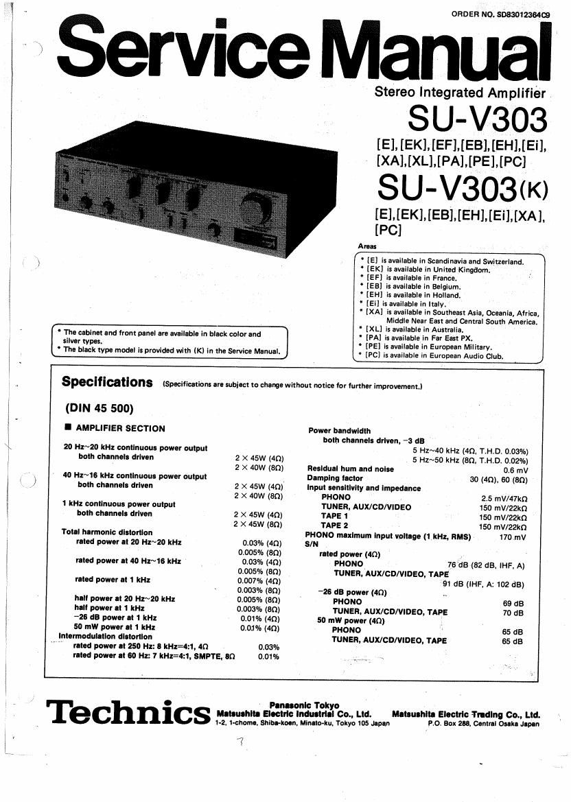
Technics SUV 303 Service Manual

This is the 18 pages manual for Technics SUV 303 Service Manual.
Read or download the pdf for free. If you want to contribute, please mail your pdfs to info@audioservicemanuals.com.

Page: 1 / 18
left right
Technics SUV 303 Service Manual

Extracted text from Technics SUV 303 Service Manual (Ocr-read)


Page 1

ORDER NO. soaaoiéasaca

Service Manual

Stereo Integrated Amplifier

SU-V303

iEi [EKi [EF] [EB] [EH] iEii
[XA] ,,[XL] [PA], [PE], [PC]

SU- V303(K)

[El 1,.[EK] [EB] [EH] [Ei] [XA].
[PC]

Areas

-. ' [E] is available in Scandinavia and Switzerland.
,) " [EK] is available in United-Kingdom;
" [EF] is available in France.
[E8] is available in Belgium.
[EH] is available in Holland.
[Ei] is available in Italy.
[XA] is available in Southeast Asia, Oceania, Africa,
Middle Near East and Central South America.

W

' [XL] is available in Australia.
r' Tre cabinet and front panel are available in black color and s [PA] is available in Far East PX.
5: var types. " [PE] is available in European Military.
Lrhe black type model is provided with (K) in the Service Manual. . [pc] 55 available in European Audio Club. J

specificat'ons (Specifications are subject to change without notice for further improvement.)

(DIN 45 500)

I AMPLlFIER SECTION Power bandwidth ,
both channels driven, -3 dB

20 H1~20 kHz continuous power output 5 Hz~40 kHz (40, T.H.D. 0.03%)

; both channels driven 2 X 45W (40) 5 Hz~50 kHz (30, T.H.D. 0.02%)
i 2 X 40W (an) Residual hum and noise 0.6 mV
,r -\ 40 Hz~16 kHz continuous power output > Damping lactor 30 (4o). 60 (an)
( , ,1 both channels driven 2 X 45W (4n) input sensitivity and impedance
2 X 40W (80) PHONO 2.5 mV/47kQ
1 kHz continuous power output TUNER, AUX/CD/VIDEO 150 mV/22kn
both channels driven 2 X 45W (40) TAPE 1 150 mV/22kn
2 X 45W (80) TAPE 2 150 HIV/22kt)
Total harmonic distortion PHONO maximum input voltage (1 kHz, HMS) 170 mv
rated power at 20 Hz~20 kHz 0.03% (40) SIN
. 0.005% (80) rated power (40)
rated power It 40 Hz~16 kHz , 0.03% (4D) PHONO - 76 dB (62 dB, iHF A)
0.005% (80) TUNER, AUX/CD/VIDEO, TAPE
3 rated power at 1 kHz 0.007% (40) 91 dB (IHF, A: 102 dB)
' * 0.003% (an) ~28 (13 power (40) N
; hell power It 20 Hz~20 kHz 0.005% (89) PHONO 69 dB
5 hell power It 1 kHz 0.003% (80) TUNER, AUX/CD/VIDEO, TAPE 70 dB
-26 dB power at 1 kHz 0.01% (40) 50 mW power (40)
50 mW power It 1 kHz 0.03% (40) PHONO 65 d8
intermoduletlon dlltortlon TUNER. AUXICD/VIDEO, TAPE 65 dB
L rated power at 250 Hz: 8 kHz=4z 1, 40 0.03%
riled power at 60 Hz: 7 kHz=4:1, SMPTE, 80 0.01% ,

0 Pen-conic Tokyo V
I C 111: mumm- Electric Industrial Co., Ltd. momma. Electric Trotting Co., Ltd.
1-2, i-cnome. snipe-km. Minute-kn. Yokyo 105 down Po Box 258. Central Osaka Japan

. y 7

Page 2

u-v303 . SU-V303

I LOCATION OF CONTROLS


Recordingmode selector .
(tape dubbing 2 F 1/1 F 2/off/phono/tuner/aux, CD. video)

input selector
itape2/tapei Iphono/tuner/aux, CD, videol

Speaker selector
(speakers off/main/remota/main and remote)

Output indicators

P°W°' Volume control

_ .VComputer-drive monitor
indicators

Headphones iack (Bass) (Treble)


Balance control
Loudnessi 1 off; _ on)

Tone controls

Subsonic filter ( h off, .. on)

Tone switchl l defeat, a. on)

Main speaker terminals


(Switched)
(Unswitched)

AC outlets

(For [XA].[PA],
iPEland [PC]
areas only)

Voltage selector

(on the bottom board) '

, . (For [XAMPAIJPE] and
3 . [Pcl areas only). ;

Remote speaker terminals

0 The power supply for this unit varies depending upon the areas. Also, the parts used for power supply are different.
So, refer to the circuit diagram and the replacement parts list.

220V (50/60Hz) for continental Europe. (Except for United Kingdom)

240V (SO/GOHZ) for Australia and United Kingdom.

1 10V/120V/220V/240V (50/60Hz) for other areas. (For other areas are provided with voltage selector)

Phono input capacitance is about 150pF.

t*¥*

I PROTECTION CIRCUITRY

The protection circuitry may have operated if eigher of
the following conditions is noticed:

0 No sound is heard when the power is turned on.

0 Sound stops during performance.

The function of, this circuitry is to prevent circuitry
damage if, for example, the positive and negative speaker
with an impedance less than the indicated" rated im-
pedance of the amplifier are used.

if this occurs, follow the procedure outlined below:

1. Turn off the power.

2. Determine the cause of the problem and correct it.

3. Turn on the power once again

Note: _

When the protection circuitry functions the unit will not
operate unless the power is first turned off and then on
agaIn. .

- Tone controls

Subscnlc filter .

I GENERAL

Frequency response
' PHONO FllAA standard curve
« i0. 8 dB (30 Hz~15 kHz)
TUNER, AUX/CDIVIDEO TAPE 5 Hz~140 kHz (-3 dB)

' +0 dB, -0. 2 dB (20 Hz~20 kHz)

Power consumption 340w

Power supply
For Australia AC 50 Hz/60 Hz, 240V
For continental Europe AC 50 Hz/SO Hz. 220V
For others AC 50 Hz/GO Hz, 110V/120V/220V/240V
Dimensions (WXHXD) 430 X 109 X 290 mm
(16-15/16" X 4-9/32" X 11- 43/32")

50 Hz, +10 dB~ -10 dB
20 kHz, +10 dB~ -10 dB
30 Hz, -6 dB/oct.

eAss
TREBLE

Loudness control (volume at -30 d3) 50 HZ: 1 9 d3 Weight 6 7 kg

Output voltage and impedance (1.4 8 lb. )
REC our 150 mV_,

Channel balance, AUX/CD/VIDEO 250 Hz~6,300 Hz :t1 dB, I Note: *

Channel SEPBIOIIOHI AUX/CD/V'DEO 1 kHz 53 dB, Total harmonic distortion is measured by the digital spectrum

Headphones output level and Impedance

42o mV/3300'_
Load Impedance . . . ,y

_ analyzer (H..P 3045 system)
4041604" , , ' " I ,

MAIN or REMOTE ' _
MAIN and REMOTE 80";160
NTENTS '

I co Page Page
SAFETY PRECAUTION ................... 2 PRINTED CIRCUIT BOARDS ............... 15~13
LOCATION OF CONTROLS ................ 3 TERMINAL GUIDE OF TRANSISTORS,

PROTECTION CIRCUITRV .................. 3 DIODES AND IC'S .................... 17
BEFORE REPAIR AND ADJUSTMENT ......... 4 FUNCTION OF TERMINAL
DISASSEMBLY INSTRUCTIONS ., ............ 4N6 (ICQ CONTROLLER IC702) .............. 18
MEASUREMENTS AND ADJUSTMENTS ........ 6,7 BLOCK DIAGRAM ...... . . . . . . 19,20
TECHNICAL INFORMATION ............... 8. 9 sci-IEMATIC DIAGRAM ................... 21~25
OPERATION OF iCO CONTROLLER .......... 1012 RESISTORS BI CAPACITORS ............... 27
CIRCUIT BOARDS AND REPLACEMENT PARTS LIST'. . . . . .......... 28
WIRING CONNECTION DIAGRAM (Top View) . . 13. 14 EXPLODED VIEWS ...................... 29, 30

SAFETY PRECAUTION

. Before servicing (such as replacement of components), unplug the power supply cord to prevent an electric shock.

cow-- 0

. Use only manufacturer s recommended components for safety. Check condition of power cord and replace if wear or

damage is evident. _

. After servicing, be sure to restore the following to the condition in which they were originally installed.

(1) the lead dress and
(2) insulation barriers, insulation papers, shields and the like.

. Before returning a serviced apparatus to a customer, make the following insulation resistance test to prevent a customer

from being exposed to a shock hazard.

Insulation resistance test (See figure below. I

. Unplug the power supply cord and connect a jumper wire between the two prongs on the plug.

. Turn on the power switch of the apparatus.

. Measure the resistance value (with an ohmmeter) between the jumpered AC plug and each exposed metalic cabinet part on
the apparatus, such as screwheads, antenna, control shafts, handle brackets, etc. > , _
The reading should be as shown in figure below. in case a measurement is outside of the limits specified, there
is a possibility of a shock hazard and the apparatus should be repaired and rechecked before it is returned to a customer.

Turntable, Amplifier etc

Tuner, Receiver etc.

Antenna
terminal

Exposed Exposed
metal metal
part part

Ohmmeter
3M9 < R< 5.2 M9

R = nearly on

where, R: resistance value . J