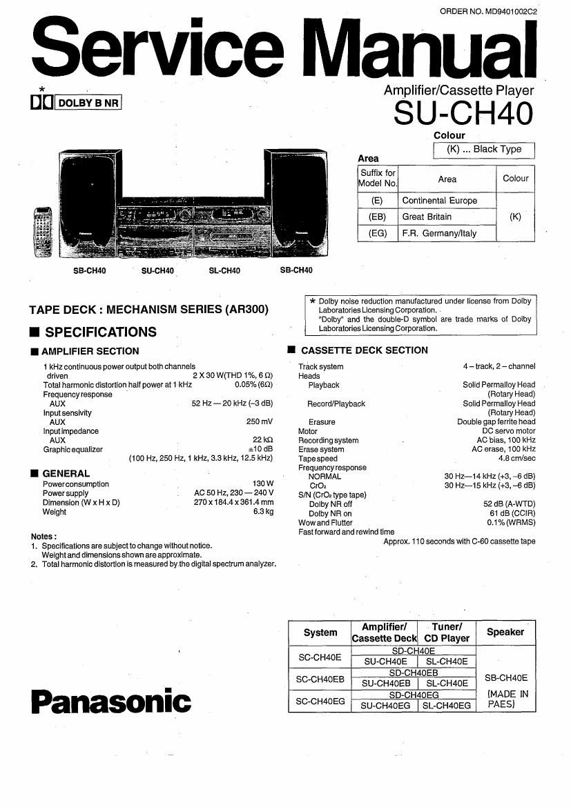
Technics SUCH 40 Service Manual

This is the 36 pages manual for Technics SUCH 40 Service Manual.
Read or download the pdf for free. If you want to contribute, please mail your pdfs to info@audioservicemanuals.com.

Page: 1 / 36
left right
Technics SUCH 40 Service Manual

Extracted text from Technics SUCH 40 Service Manual (Ocr-read)


Page 1

ORDER NO. M0940100202'

Service , anual

Amplifier/Cassette Player

u_ * , SU-CH4O

Colour
(K) Black Type
Area

(E) Continental Europe
(EB) Great Britain (K)
(EG) F.Fi. Germany/Italy

SB-CI-MO SU-CH4O . SL-CH4O SB-CH40
I * Dolby noise reduction manufactured under license from Dolby
TAPE DECK I MECHANISM SERIES (AR300) Laboratories Licensing Corporation. .
"Dolby" and the double-D symbol are trade marks of Dolby
I SP EC I FICATI ON 3 _ Laboratories Licensmg Corporation.
I AMPLIFIER SECTION ' I CASSETTE DECK SECTION
1 kHz continuous power output both channels ' Track system 4 - track, 2 - channel
driven 2 X 30 W(THD 1%, 6 9) Heads
Total harmonic distortion half power at 1 kHz 0.05% (69) Playback Solid Permalloy Head
Frequency response ' (Rotary Head)
AUX 52 HZ - 20 kHZ (-3 d3) Record/Playback Solid Permalloy Head
Input sensivity (Rotary Head)
AUX 250 mV Erasure Double gap ferrite head
lnputimpedance Motor DC servo motor
AUX . 22 k9 Recording system . AG bias, 100 kHz
Graphic equalizer :10 dB Erase system AC erase, 100 kHz
(100 Hz, 250 HZ, 1 kHz, 3.3 kHz, 12.5 kHz) Tapespeed 4.8 omlseo
Frequency response
I GENERAL , NORMAL so Hz-14 kHz (+3, ~6 dB)
Powerconsumption _ 130 W 0,02 30 Hz-1 5 kHz (+3, -6 dB)
Power supply , AC 50 H2, 230 - 240 V S IN (0,02 type tape)
Dimension (W X H x D) 270 X 184.4 X 361.4 mm Dolby NH Off ' 52 dB (A-WTD)
Weight 6-8 k9 Dolby NR on 61 dB (CClFi)
Wow and Flutter 0.1% (WRMS)

Fast forward and rewind time

Notes 3 Approx. 1 10 seconds with C-60 cassette tape

1. Specifications are subject to change without notice.
Weight and dimensionsshown are approximate.
2. Total harmonic distonion is measured bythe digital spectrum analyzer.

Amplifier] Tunerl '
System Cassette Deck CD Player Speaker
~ SD-CH4OE
SCCH40E SU-CH4OE l SL-CH4OE
SD~CH4OEB SBCHME

SC-CH40EB SU-CH4OEB I SL.CH4OE
(MADE IN

I
P SD-CH4OEG
anasonlc SCCH4OEG SU-CH4OEG | SL-CH40EG PAES)

Page 2

SU-CH40

I CONTENTS

ACCESSORIES ...............
PROTECTION CIRCUITRY.
BEFORE HEPAIRANDADJ
CAUTION FOR AC MAIN LEAD..
CONNECTIONS ....................
FRONTPANELCONTHOLS AND FUNCTIONS
DISASSEMBLY INSTRUCTIONS} ...........
MEASUREMENTS AND ADJUSTMENTS
TESTMODE INSPECTION.
TERMINAL FUNCTION OFI .
BLOCK DIAGRAM .....................


I ACCESSORIES


SCHEMATIC DIAGRAM ........................................... , .......
TERMINAL GUIDE OF IC's TRANSISTORS AND DIODES.
WIRING CONNECTION DIAGRAM.
PRINTED CIRCUIT BOARD ........
MECHANISM PARTS LOCATION (DECK1)

(DECK2)
CABINET PAFITS LOCATION...
REPLACEMENT PARTS LIST
RESISTORS&CAPACITOFIS..
PACKAGING.

FOR ONLY E. E6 Area
AC Power Supply Cord : RJA0019-2K ..................... 1 pc.

FOR ONLY EB area
AC Power Supply Cord : VJA0733 ................. 1 pc.

Remote control transmitter : EUR642182 ............. 1 pc. Remote control batteries : UM-4. AAA, R08 ......... 2 pCS.
I I
I I
l I
I I
LW/MW loop antenna I Antenna Holder I Screw
SLASZsT .............. 1 pc.] RMN0244...1pct |XTN3+12AFZ ...... 1pc. Flat Cable : REX05811pc
FOR ONLY EG area
FM Indoor Antenna : SSA270M ................................... 1pc. Attachment Plug : SJFQOOQ ................................... 1pc.

I PROTECTION CIRCUITRY

The protection circuitry may have operated If either of
the following conditions are noticed:

- No sound Is heard when the power is turned on.

- Sound stops during a performance.

The function of this circuitry is to prevent circuitry damage
if, for example, the positive and negative speaker
connection wires are "shorted", or if Speaker systems with
an impedance less than the indicated rated impedance of
the amplifier are used.

if this occurs, follow the procedure outlines below:

1. Turn off the power.

2. Determine the cause of the problem and correct it.
3. Turn on the power once again after one minute.

Note:
When the protection circuitry functions, the unit will not
operate unless the power is first turned off and then on
again.

Page 14

SU-CH40

Test [3]: TPS FUNCTION

(1) Press [3] key.

* Input selector will set to "TAPE".

* Volume level will set to "-20 dB".

* Reverse mode will set to "Z" (1 way).

* F-REWTPS will seton deck 1. (FWD-PLAY~REW).

* Deck 1 will stop at the beginning of the present
program.

* R-FF TPS will set on deck 2. (REV-PLAY~FF)

* Deck 2 will stop at the beginning of the present
program.

Test [4]: REVERSE MODE FUNCTION
(1) Press [4] key.
* Input selector will set to "TAPE".
* Volume level will set to -20 dB.
* REV mode will set to (:f' (REPEAT) mode.
* Deck 1 will start to REV-PLAY.
* Deck 2 will start to FWD-PLAY at D1 tape end.

Test [6]: TAPE RECORDING THROUGH AUX INPUT

(1 ) Press [6] key.
* Selector position will set to [AUX].
*volume level will set to "-20 dB".
* REVERSE mode will set to " Z " (1 way).
* Tape counter will set to "000- " on deck 2
* Recording will start on deck 2.
(2) Press I (TAPE STOP) key.
* Both keys are acceptable for center unit or remote
control unit.

(2) Pressq (REV PLAY) key, the present program of deck
2 will be started soon.
(3) Press [DECK1/2] to select deck 1, and then press I>
(FWD/PLAY) key, the present program of deck 1 will be
' started soon.

Note:

The tape used on Deck 2 should have the erase
protection tabs on both sides. If not, test mode will be
cancelled.

* REV mode will start to _ __> (REVERSE) mode.
* Deck 2 will change to REV- PLAY at D2 tape end.
* Deck2 will stop a the tape end.

* REV mode will set to "Z" (1 way) mode.

* Deck .1 will start to FWD-PLAY.

* Deck 1 will stop at the tape end.

(3) Press «(TAPE REW) key.

* Tape will stop at "000-" of the tape counter.
(4) Press p (TAPE FWD PLAY) key.

Ensure the sound was recorded accurately.

Note:
The tape used on Deck 2 should have the erase
protection tabs on both sides. If not, test mode will be
cancelled.

* Test mode will be cancelled if deck 2 reaches the end.

Test [7] : TACT SWITCH AND FL DISPLAY CONNECTION

(1) Press [7] key.
* FL display will light out.
(2) Press any key one by one.
* FL display will indicate on each segment.

Test [8] :

' (1) Press [8] key.
* FL display will indicate same as TEST U].

Test [9] : VOLUME MAXIMUM

(1) Press [9] key.
* Volume level will be set to maximum.
* "ed a " will be displayed in 2 sec.

Test [0] : VOLUME MINIMUM

(1) Press [0] key.
* Volume level will be set to minimum.
* "-d a" will be displayed in 2 sec.

(3) After all of the keys were pressed, all segments of the
FL display will on.
([POWER] key has no effect)

(4) Press [POWER] key or [CD STOP] key on the remote
control unit to exit from the test mode.

ALL SEGMENTS OF FL DISPLAY LIGHTS ON

_.14_