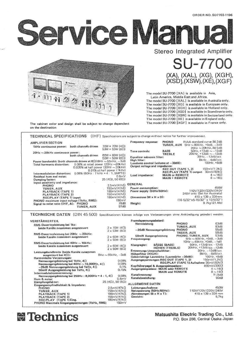
Technics SU 7700 Service Manual

This is the 9 pages manual for Technics SU 7700 Service Manual.
Read or download the pdf for free. If you want to contribute, please mail your pdfs to info@audioservicemanuals.com.

Page: 1 / 9
left right
Technics SU 7700 Service Manual

Extracted text from Technics SU 7700 Service Manual (Ocr-read)


Page 2

I ALIGNMENT INSTRUCTIONS

. When the power transistor is replaced, be sure to apply silicone compound (or equivalent thermal diffusion agent) onto
the mica plate, and at the same time confirm the idling current of the power transistor. (measure voltage across the
emitter resistance)

at) For adjustment with DC voltmeter

1. Turn the speaker switch "OFF'K

2. Connect the DC voltmeter as in Fig. 7 of the adjusting spot diagram.

3. If the reading is under 25mV approximately several minutes after turning ON the power supply, the circuit is OK".
On the other hand, if the reading is over 25mV, cut off the lead wire for L in the case of left channel (The lead
wire for R in the case of right channel),

4. Should the reading not fall under 25mV even when the lead Wire has been Cut off, there is something wrong with the
circuit, and therefore, check the power source Circuit or main amplifier circuit.

NOTE' When cutting off the lead wire, cut off the same at the root.

(B) Current should be checked only when adjustment is made with a tester. (measuring instrument incapable of measur-
ing voltage in mV unit).

1. Turn OFF the power supply for the set.

2. Connect the ammeter as shown in Fig. 9.

3. After ensuring that the ammeter will not come off, turn ON the power supply.

4, lf the reading is under 75mA after serveral minutes (But, when nothing resistance of internal resistor by ammeter) the
Circuit is "O K". If over 75mA, cut off the lead wire for L in the case of left channel (The lead wire for R in the case
of right channel).

5. lf the reading does not fall under 75mA, there is something wrong With the circuit.

NOTE The adjustment may be made either by (A) or by G!) method. (We recommend the method 63) where possible).
Figs. 8 and 9 are related to the case of left channel.

fl '--- '- +3 DC VOLTMETER +3 DC AMMETER

(ill U lllllllllll

§

-B *B


Voltage check method Current check method
23, Lésfhan (Stromspannung»prllfmethode) (Stromstzirke-Prflfmemode)
DC 25mv DC zsmv Méthode de verification Méthode de vérlfication
( de tension de courant
~2 .
E Fig. 8 (Abb. 8) Fig. 9 (Abb. 9)

Fig. 7 (Abb. 7)
I ABGLEICHANWEISUNGEN

- Wenn der Netztransistor ersetzt wird, ist zu beachten, dais eine Siliziumverbindung (oder ahnliches Thermodifiusions-
mittel) auf die Glimmerplatte gegeben wird, und zur gleichen Zeit der Blindstrom des Netztransistors festgestellt wird..
(Die Spannung uber den Emitterwiderstand messen.)

(3 Zum Justieren mit dem Gleichstrom-Voltmeter

1. Drehen Sie den Lautsprecherschalter auf "OFF,

2. Schlielsen Sie den Gleichstrom-Voltmeter an, wie in Abb. 7 des Justrerpunkte-Diagramms gezeigt.

3. Falls die Anzeige weniger als ca. 25 mV betragt, so is! die Schaltung in Ordnung. Falls aber die Anzeige mehr als
25 mV betragt, sehneiden Sie den Leitungsdraht fiir L im Palle des linken Kanals weg ( oder den Leitungsdraht fi'ir Fl
im Falle des rechten Kanals).

4. Falls die Anzeige auch nach Unterbrechen des Leitungsdrahtes nicht unter 25 mV fallt, so ist die Schaltung nicht in
Ordnung, und die Stromquellenschaltung und die Hauptveist'arkerschaltung mUssen Uberpriift werden.

ANMER KUNG Falls das Wegschneiden des Leitungsdrahtes notig ist, schneiden Sie diesen nahe am Anschlulspunkt wag.
lZl su.77oo