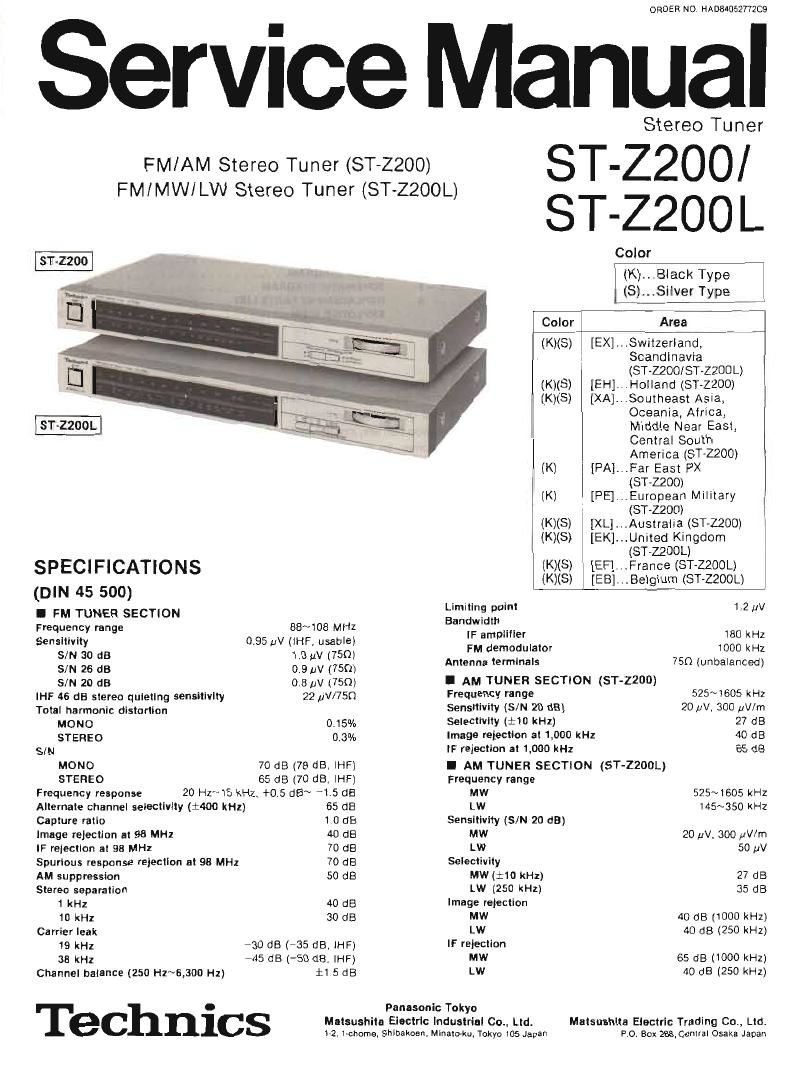
Technics STZ 200 Service Manual

This is the 12 pages manual for Technics STZ 200 Service Manual.
Read or download the pdf for free. If you want to contribute, please mail your pdfs to info@audioservicemanuals.com.

Page: 1 / 12
left right
Technics STZ 200 Service Manual

Extracted text from Technics STZ 200 Service Manual (Ocr-read)


Page 2

T-ZZOO 200

I GENERAL

Output voltage 0 3V (0.6V IHF) Dimenslons (WXHXD) 430 X 53 X 242 mm
Power consumption 5W (16-35/16" X 2-3/32" K 947/32)
Power supply Welghl 2.4 kg [5.3 lb)

For Australia and United Kingdom AC 50 Hz/60 Hz, 240V

For continental Europe

AC 50 Hz/60 Hz 220v - Specifications are sublect to change without notice for

For others AC 50 Hz/GO Hz. l1OV/120V/220V/240V further improvement.
Page Page
SAFETY PRECAUTION ....................... 2 CIRCUIT BOARDS AND WIRING CONNECTION DIAGRAM
LOCATION OF CONTROLS . , . . . t .3 MODEL ST-ZZDO ......................... 9,10


FM/AM Stereo Tuner
(ST~ZZOO)

FM/MW/LW Stereo Tuner
(ST-ZQOOL)

DR DER NO. HAD84052772CQ»A

ST-ZZOO/ ST-ZZOO L

This booklet includes the specifications and adjustment of Model STZZOO/STZZODL (Order No. HA084052772C9l
Written in German, French and Spanish.
File this booklet together with the service manual of Model ST~ZZOOiST-ZZOOL.

Dieses Buchlein umfalSt die technischen Daten und Justierungsarileitungen von Modell STaZZOO/ST-ZZOOL (Bestell Nr.
HADS4052772C9l in den Sprachen Deutsch, Franz'osesch und Spanisch.
Bewahren Sie dieses Birchlein zusammen mit dem Service-Handbuch von Modell ST-Z200/ST-ZZOOL.

DISASSEMBLY INSTRUCTIONS ................... 1 MODEL ST-ZZOOL . . . . . ....... 11,12
DIAL CORDINSTALLATION GUIDE ................ 4 BLOCK DIAGRAM ................ 13,14
MEASUREMENTSAND ADJUSTMENTS - . , . - « 5~7 SCHEMATC DIAGRAM ----- ~ ~ - . - 15~17 Cette brochure comprend les specifications et la mise au point du Modéle ST~ZZOO/ST-Z200L (NO d'Oidre
RESISTDRSAND CAPACITORS ................... 8 REZLSCEMEN; PARTS LIST .................. 12,12: HAD84052772C9) éCrilES en allenmand,en lrancais el en espagnol,
EX L BED VI . w """"""""""""""" ' Classer cette brochure en meme temps qu'avec le manuel de service du Modele ST»ZZOD/ST-ZZOOL
I SAFETY pRECAUTION O Este lihrito incluve |as~especilicaclones y ajuste de Modelo STAZZOO/STQOOL (Pedido N9 HAD84052772C9l esrltas en
1 Before servcing unplug the power cord to prevent an electric shock. aleman, trancés Y espanol,
' ' , . O Guardar este librito iuntamente con el manual service de Modelo ST»Z,ZOO/$TVZDOL.
2 When replacmg parts, use only manufacturer 5 recommended components for safetvt
3, Check the condition of the power cord. Reolace if wear or damage is evident
4 After servicing, be sure to restore the lead dress, insulation barriers, insulation papers, shields, etc

9 i

Belore returning the serviced equipment to the custon'ier, be sure to make the following insulation resistance test to
prevent the customer from being exoosed to a shock hazard.

0 INSULATION RESISTANCE TEST
1. Unplug the power cord and short the two prongs of the plug With a jumper Wire,
2 Turn on the power switch
3. Measure the reSistance value wnh ohmmeter between the iurnoered AC plug and each exposed metal cabinet part, such as
srrewheads antenna control shafts, handle brackets, etc Equipment with antenna terminals should read between 3M9
and 5.2MQ to all exposed parts. lFig. A) Equipment without antenna terminals should read approximately infinitv to

DEUTSCH

I TECHNISCHE DATEN

(Spezilikationen Konnen infolge von Verbesserungen ohne AnkUndigurig geandert werden l

(DIN 45 500)

all exposed parts lFig B) I UKW-TUNERTEIL I MW-TUNERTEIL (ST-Z200)
N ' f h ' h | f Wellenbereich 88 ~ 108 MHz Wellenberelche 525 "r 1605 kHz
ote. Some exposed parts may be Isolated rom me C assus by demgnt T ese Wll read in inity, Eingangsemptindllcnkelt 095 W lnutzbar nach IHF) Eingangsempfindllchkeit (5/8 20 dB) 2011V- 300 mm
SIR 30 as to av (75 o) Trennschérte (:10 kHz) 27 d8
3m 25 d8 03 V (75 m Spiegellrequenz-Démplung bei 1000 kHz 40 dB
SIR 20 dB 0,8 UV (75 0) ZFADémpIung bei 1000 kHz 55 a5
Antenna Slereoumschaltschwelle bei 46 (13 neon [HF 22 uV/75 n I MW/LWTUNERTEIL (ST-ZZOOL)
[ermma' V\J f Gesamllilirrlaktor Wellenbereiche
E Mono 015% MW 525 ~ 1505 kHz
: Stereo 0,13% LW _ ~ _ 145 ~ 350 kHz
Exposed / Exposed Gerfiuschabstand Elngangsempflndlichkeil (S/R 20 dB)
Mono 70 dB (78 dB nach lHF) MW 20 av. 300 yV/m
metal melal L (
Slereo 65 as [70 GB nach lHF) W 50 LA.
Dar! part 1 h"
Frequenzgang 20 Hz N l5 kHz (+0.5 08 ~ 4.5 087 Elm 8' 9
Onmmeter Ohmmeter Trennscnarie bei starsender (:400 kHz) 65 d8 :37 (:51: $2) $2 a:
p . Einlangverhaitnis to de _ l I)»
[ lg A) F'g' BI Spiegeivrequenx-Dampiung bei 95 MHz 40 dB Splegellrequenz-Damplnng
ReSistance: 3MQ-5 EMS) FleSistance: Approx (x) ZF-Dampfung bei 98 MHz 70 dB MW 40 dB HOOD kHzl
, ,, .. .v . LW 4 BEOkHZ
4. i the measurement is OUTSIde the specnied limits, there l3 3 DOSSIbility of a shock hazard. The equipment should be Ansprechdamptung aut Nebenlrequenzen bei 93 MHz 73 d: ZF-Démplung 0 d l S l
repaired and rechecked before it IS returned to the customer. (Tlfinlegmicgurfn 5 0 MW 65 dB (1000 kHz)
11);: p g 40 as LW 40 dB i250 KHZ)
10 kHz 30 dB I ALLGEMEINE DATEN
Trggenes Ausaangsspamung 0,3 v (0,6V IHF)
19 kHz 730 dB ( 735 dB nach lHFl :jfz:::::gahm° 6W
-4 dB-OdBnathF
Kanaalilitlelichun (250 Hz ~ 6300 H115 ( 5 f1 5 dB Fifi: Kanlinentaleuropa Wechselstrom 50 Hz/SD Hz, 220v
B n mg " 2 V Filr andere Linder Wechselstrom 50 Hz/GO Hz.
Begzebnzi'e' s z ' "' llDV/lZOV/ZZOV/ZAOV
an ZFreI e t" k 180 kHz Abmessungen (B KHXT) 430 x 53 x 242 mm
~Vers ar er Gewlchl 2 4 kg
UKW-Demodulalor 1000 kHz ,
Antennenanschlufl 75 n (unsymmetriscn)