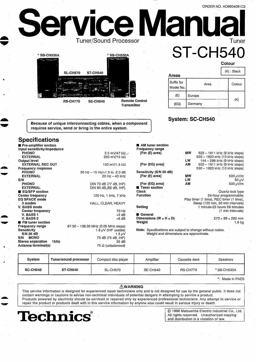
Technics STCH 540 Service Manual

This is the 32 pages manual for Technics STCH 540 Service Manual.
Read or download the pdf for free. If you want to contribute, please mail your pdfs to info@audioservicemanuals.com.

Page: 1 / 32
left right
Technics STCH 540 Service Manual

Extracted text from Technics STCH 540 Service Manual (Ocr-read)


Page 1

0

451

H

H

ORDER NO. AD960409102

Service Manual

Tuner/Sound Processor Tuner
* se-cnssoA se-cnssoA : 3 I -( : I I 5 4 (3
Colour
SL-CH570 ST CH540 (K) : Black
Areas
Suffix for Area Colour
Model No
' 1- (E) Europe
HS-CH770 SE-CH54O Remote Control (K)
' Transmitter (EG) Germany

System: SC-CH54O

Because of unique interconnecting cables, When a component
requires service, send or bring inthe entire system.

Specifications
I Pre-ampliiier section
Input sensitivity/impedance

I AM tuner section
. Frequency range
2.5 mV/47 k9 /

FHONO [For (E) area] MW 522- 1611 kHz (9 kHz steps)
EXTERNAL 250 mV/15 k9 530-1820 kHZ (1 0 kHz steps)
Output level _ LW 144- 288 kHz (9 kHz steps)
EXTERNAL REC our 150 mV/1,5 ks; [For (EG) area] AM 522- 1611 kHz (9 kHz stepSl
Frequency response 530 - 1620 kHz (1 0 kHz steps)
PHONO so Hz - 15 Hz/+1.5 to -2.o dB Sensitivity (SIN 20 dB)
EXTERNAL 20 Hz - 40 kHz [For (E) area] MW 500 ,uV/m
s/N Lw so uv
PHONO DIN 73 dB (77 dB, lHF) [For (EG) area] AM 500 uV/m
EXTERNAL DlN 80 £15,632 dB, lHF) I Timer section
I EOISFP section Clock Quartz-lock type
Center frequency 120 Hz, 1 kHz, 7 kHz Function 24-hour programmable;
EQ SPACE mode Play timer (1 time), REC timer (1 time),
3 modes HALL, CLEAR, HEAW Sleep (120 min_ 30 min intervals)
V. BASS mode Setting 1 minute-23 hours 59 minutes
Center lrequency 70 Hz - (1 min intervals)
V. BASS 1 +3 dB I General
V. BAssz +6 dB Dimensions (W x H x D) 270 x 89 x 282 mm
I FM tuner section Weight 1.6 kg
Frequency range 87.50 - 10800 MHz (005 MHz steps) v
Sensitivity 1,8 pV (IHF usable) Note: Specifications are subject to Change without notice
SM 26 dB 1.5 v Weight and dimensions are approximate.
S/N MONO 70 dB (75 dBx lHF)
Stereo separation 1kHz 35 dB
Antenna terminal(s) 75 $2 (unbalanced)
System Tuner/sound processor Compact disc player Amplifier Cassette deck Speakers
SC-CH54Q ST-CH540 SL~CH570 SE-CH540 HSvCH77O * SB-CHSSOA
*: Made in PAES
AWARNING
This service iniormation is designed for experienced repair technicians only and Is not designed for use by the general public It does not
contain warnings or cautions to advise non- -technical individuals of potential dangers In attempting to service a product.
Products powered by electricity should be serviced or repaired only by experienced professional technicians. Any attempt to service or
repair the product or products dealt with in this service information by anyone else could result in serious injury or death

Technics®~

© 1996 Matsushita Electric industrial Co.. Ltd.
All rights reserved Unauthorized copying-
and distribution is a violation of law,

Page 2

ST-CH540

l Contents

Page Page
Location of Controls . Printed Circuit Board Diagram 18~21
Setting the Time.... 2 Wiring Connection Diagram ..... 21


About the Self-Diagnostic Mode 5 Block Diagram... . 22~25
Operation Check and Function of IC Termina s. ..... 26

Main Component Replacement Procedures . 4 Replacement Parts List 27~31
To Supply Power Sourse ............................. 5 Cabinet Parts Location
Schematic Diagram .......... 6~17

NOTE:
Refer to the service manual for Model No. SE-CH540 (ORDER No. AD960409202) for information on Accessories,
"Stacking the Components, Connections and Packaging.

I Location of Controls

@Source input select button (SELECTOR)

®Remote control signal sensor (SENSOR)

®Karaoke button ((KARAOKE)

@Tuning/timer select button (TUNING/TIMER, A,V)

@Set button (SET)

@Record timer button (6 REC)

@Play timer button (6) PLAY)

.FM mode select button (FM, -AUTO/MONO)

@Tuner indicator (TUNER)

@LW/MW select button (LW/MW) . .for (E) area

6 8 9 > AM button (AM) ............................ for (EG) area
- @Tuning mode select button (TUNING MODE)

@CIock/tlmer button (CLOCK/TIMER)

I Setting the Time

This is a 24- hours display clock
These instructions explain how to set the timer for 16: 25 (4: 25 p. rn ) on
Wednesday
1 Switch on the power. 2
2 ® Press CLOCK/TIMER to show CLOCK".
Within 8 seconds:
(2) Press SET.
3 6) Press TUNING/TIMER (V or A) to select the day.
® Press SET.

4 ® Press TUNING/TIMER (V or A) to select the hour. . ,
(2 Press SET. ' ....

E: . __ _.
(D Press TUNING/TIMER (v or A) to select the 8 T6 0 C>=Q
minutes. u

(D Press SET to finish settIng the time. - 1 2 3

The display will return to the previous display after about 3
seconds rowan ' ® ® (D mums/men Q)

When SUN 0:00" flashes: . smumg >

it flashes when you connect the AC power supply cord for the first time
or it there has been a power failure.
If this happens, reset the time,

lO

UI

If the minutes setting has gone wrong:
1, Press CLOCK/TIMEHP

2. Press SEl 3 times. > 4 V ' 5
3. :rEezss TUNING/TIMER (V or A) to set the minute and then press mums/mien (D TUNING/TIMER ®

v A

To display the clock again:
Press CLOCK/TIMER.
The clock display will appear for about 8 seconds.

I
.....\..:. E/
I III
eye-K ......

n...

For Your reference:
When you turn OFF the power from the POWER button. the stereo
goes on standby and the STANDBY lamp lights up.

0

U

i t