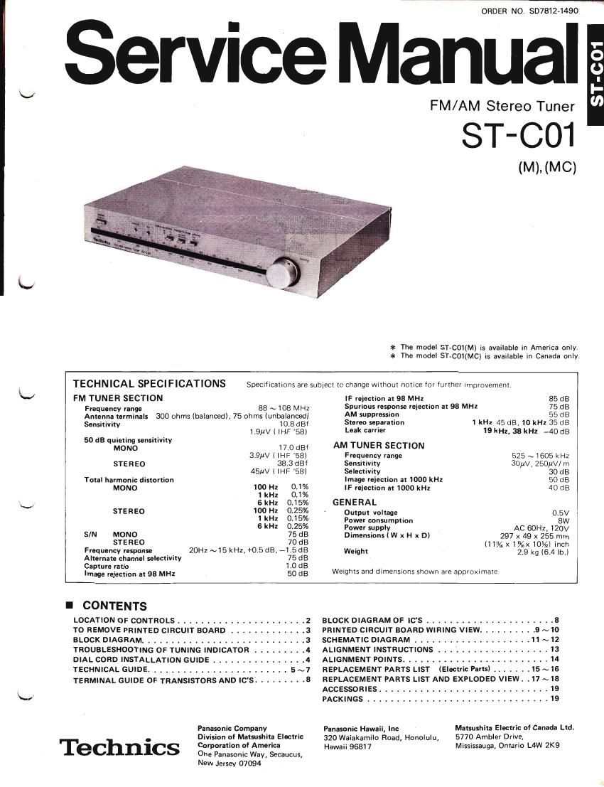
Technics STC 01 Service Manual

This is the 20 pages manual for Technics STC 01 Service Manual.
Read or download the pdf for free. If you want to contribute, please mail your pdfs to info@audioservicemanuals.com.

Page: 1 / 20
left right
Technics STC 01 Service Manual

Extracted text from Technics STC 01 Service Manual (Ocr-read)


Page 1

-_

ORDER NO. SD7812-1490

ervice Manual

FM/AM Stereo Tuner

ST-CO1

(M). (MC)

:1: The model ST-C01(M) is available in America onlyv
al: The model ST-C01(MC) is available in Canada only


TECHNICAL SPECIFICATIONS Specifications are subject I0 change without notice for further improvemenii
FM TUNER SECTION IF rejection at 98 MHz 85 dB
Frequency range 88 A, 108 MHz Spurious response rejection at 98 MHz 75 dB
Antenna terminals 300 ohms (balanced), 75 ohms (unbalanced) AM supp'OSion 55 dB
senfifimy 103 dBf Stereo separation 1 kHz 45 dB, 10 kHz 35 dB
1.9;1V ( IHF 58) Leak carrier 19 kHz, 38 kHz -40 dB
50 dB quieting sensitivity
MONO 17_0 dBf AM TUNER SECTION
3.9}1V l IHF 58) Frequency range 525 ~1605 kHz
STEREO 38,3 dBf Sensitivity 30AV4 ZSOflV/ m
45MV l IHF '58) Selectivity 30 dB
Total harmonic distortion Image reiection at 1000 kHz 50 dB
MONO 100 H: 0.1% IF rejection at 1000 kHz 40 dB
1 kHz 0.1%
GkHz 0.15% GENERAL
STEREO 00 H1 025% ' Output voltage 0.5V
I k! (115% Power consumption 8W
5 k"! 025% Power supply AC eon, 120v
SIN MONO 75 dB Dimensions I W x H x D) 297 x 49 x 255 mm
STEREO 7MB l11'sz19gx10lfil inch
Frequency response 20Hz ~15 kHz. +0.5 dB, -1.5 dB Weight 29 kg (6.4 lb)
Alternate channel selectivity 75 dB '
Capture ratio 110 dB . . . .
Image rejection at 93 MHz 50 dB Weights and dimensmns shown are apprommaie
I CONTENTS
LOCATION OF CONTROLS ...................... 2 BLOCK DIAGRAM OF IC'S ...................... 8
TO REMOVE PRINTED CIRCUIT BOARD ............. 3 PRINTED CIRCUIT BOARD WIRING VIEW .......... 9 ~10
BLOCK DIAGRAM .................. SCHEMATIC DIAGRAM .............. . , . 11 ~12
TROUBLESHOOTING 0F TUNING INDICATOR . ALIGNMENT INSTRUCTIONS . . . . . . i ...... 13
DIAL CORD INSTALLATION GUIDE ...... . . . . ALIGNMENT POINTS .......... . . . ...... 14
TECHNICAL GUIDE ................. . . . . 5 ~7 REPLACEMENT PARTS LIST (Electric Parts) ....... 15 ~16
TERMINAL GUIDE 0F TRANSISTORS AND IC'SL ........ 8 REPLACEMENT PARTS LIST AND EXPLODED VIEW . .17 ~18
ACCESSORIES ............................. I9
PACKINGS ............................... 19
Panasonic COMPMY Panasonic Hawaii, Inc Matsushita Electric of Canada Ltd.

Division of Matsushitn Filmtric 320 Waiakarnilo Road, Honolulu, 5770 Ambler Drive,

I I elchnics Corporation of America Hawaii 95317 Mississauga, Ontario L4W 2K9
One Panasonic Way, Secaucus,

New Jersey 07094

Page 2

m

I LOCATION OF CONTROLS

Active servo lock indicator |-Aclive servo lock switch(lon - off)

FM stereo indicator- FM muting/mode switch(lon/auto -off/mono)

Power switch

Band selector switch( [FM -AM)

m z I

«in»

Ir-Itlnvl

we,

m ,, . .3, . ,9, i m . .9.
Mains mmumm- 5mm
J

Dial pointer & Tuning indicator

mum same mm _

3009 759

J GND
AM antenna terminal --'-I

FM antenna lerminals

OUtPUt terminals AM bar amenna coil

FM IF amplifier

81 AM converter FM RF circuitry

FM multiplex .
unit-«-
a 0

. I . ,.
FM IF amplifier

Power supply

. regulalor
Tuning

indicator circuitry

Active

. . Power transformer
servo lock curcumy

Page 5

l TECHNlCAL GUIDE 3. DeVIa'

(A) ACTIVE SERVO LOCK CIRCUIT 'f "9

This circuit is designed to maintain the exact tuning point even in case of frequency drift in the set or at the broadcasting 2:259:

statIon.

lt watches the 8 curve of the FM IF detector and 63 Q's/Power MW 4 0:22;);

shifts the voltage to its original level if it is deflected -

from the reference voltage thus keeping the set in g 19 % g H i
_ . . _ R303 Doaos R309 R306 rim of m

optimum Tuned condltlon at all tImes. RH 100k (5W, .0, _

1. No signal reception mode Eff 32302 km, $3., we"
|C301 is dual operational amplifier plus voltage 1 i16V33 030.3 f

. R113

amplifier. mg MOD
A reference voltage of about 5.6V is applied camf 9 3 N 030 03
from terminal 63) of |C102 to terminal ® of v 3 3 é 05
|C301. The IF detector output voltage is fed L ' ngc
from terminal (D of |C102 to terminals © and '°w°'mg" jU_~'
® of l0301. (Since this unit is a quadrature 4%7ajgfirgggw 3 IFSREE
detection type, the output voltage at terminal @ m Rue 53353;, W
is about 5.6V in No signal" and "Exact tuned OUTPUT iNPUT | 15 LC
condition.) 9 0 + (B) TUl
lC301 detects the difference between the E Th 5
detector output voltage and the reference voltage R306 0 9 9 Sim
to obtain an amplified difference voltage at M l ,NPUT crrc
terminal ® of |C301. No s-snal made mm ourPu'r 1 1
This voltage controls 0309 which is turned off in 6 - I
the Exact tuned and in the No Signal" mode, (
(Reference voltage and detector output voltage m"? "we mos I
are the same.) C
0101 located near IClOZ is a switching transistor Ame 58W lock (53) Gm Up cmcw o; a
to operate in accordance with the FM-IF signal 1°" WWW 2 5
level. -
It is ON in the "No signal" mode as its base (Active 599° lzck circuit) 1
potential is high at that time, and it turns OFF '9' C
only, when the input level of the FM-IF signal V
reaches a certain level. a

With the active servo lock switch ON", and 0101 ON", both the collector voltage of 0101 and the base voltage of
0307 are 0V (ground potential), while 0307 is OFF.

Consequently, 0308 is ON, 0311 is OFF and 0310 is ON, and voltage is being applied to the variable capacity diode
D1 as in Fig. 5.

N

Signal reception mode

As explained above, 0101 turns OFF when a signal is received, causing the collector voltage to rise. D103 is
reverse-biased and current stops to flow. In other words, the base of 0307 is electrically disconnected from the
collector of 0101 .

This causes 0301 to be charged through R303. About 2 or 3 seconds later, 0307 turns ON and the servo lock circuit
starts to operate.

Then, servo lock indicator D305 light up.

When 0307 is ON, then 0308 is OFF, 0311 is ON and 0310 is OFF and a constant voltage is applied to D1 as shown
in Fig. 6.

R11 R11 R11

OSC 080

R314

a) O)
E, $ 3 +v
'7 5 § (12v)
E 3 E
(5,6V) (5.6V)
(No signal mode) (Exact tuning 8: (Deviation to higher frequency)
Fig. 5 deviation to lower frequency) Fig. 7

Fig. 6