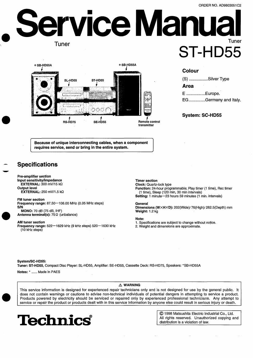
Technics ST HD 55 Service Manual

This is the 28 pages manual for Technics ST HD 55 Service Manual.
Read or download the pdf for free. If you want to contribute, please mail your pdfs to info@audioservicemanuals.com.

Page: 1 / 28
left right
Technics ST HD 55 Service Manual

Extracted text from Technics ST HD 55 Service Manual (Ocr-read)


Page 1

\

. Service Manual

ORDER NO. AD9803051CZ

Tuner
Tuner
:1: SB-HD55A , * se-HoasA
Colour
(S) ................ Silver Type
Area
E ................ Europe;
EG .............. Germany and Italy.
System: SC-HDS5
Remote control
transmitter
Because of unique interconnecting cables, when a component
requires service, send or bring in the entire system.
Specifications
Pre-amplifier section
input sensitivity/impedance Timer section
EXTERNAL: 300 mV/15 k0 Clock: Quartz-lock type
Output level Function: 24-hour programmable; Play timer (1 time), Rec n'mer
EXTERNAL: 25D mV/1.5 kit (1 time), Sleep (120 min, 30 min intervals)

Setting: 1 minute-23 hours 59 minutes (1 min. intervals)
FM tuner section

Frequency range: 8750-10800 MHz (0.05 MHZ steps) General
SIN Dimensions (WXHXD): 202(Wide)/ 76(High)/ 262.5(Depth) mm
MONO: 70 dB (75 dB, IHF) Weight: 1.2 kg
Antenna terminal(s): 759 (unbalance)
Note:
AM tuner section 1. Specifications are subject to change without notice.
Frequency range: 522-1629 kHz (9 kHz steps) 520-1630 kHz 2. Weight and dimensions are approximate.

(10 kHz steps)

System/Sc-HDSS:
Tuner: ST-HD55, Compact Disc Player. SL-HD55, Amplifier: SE-HD55, Cassette Deck: RS-HD75, Speakers: SB-HD55A

Notes: ' ...... Made in PAES

A WARNING
This service information is designed for experienced repair technicians only and is not designed for use by the general public. it
does not contain warnings or cautions to advise non-technical individuals of potential dangers in attempting to service a product.
Products powered by electricity should be serviced or repaired only by experienced professional technicians. Any attempt to
service or repair the product or products dealt with in this service information by anyone else could result in serious injury or death.

© 1998 Matsushita Electric Industrial 00., Ltd.

. ® All rights reserved. Unauthorized copying and
ec nlcs distribution is a violation of law.

Page 2

ST-HD55

IAbout the Sent-Diagnostic Mode

This unit is equipped with a self-diagnostic function which, in the event of a malfunction, automatically displays a code indicating the
nature of the malfunctions. Use this self-diagnostic function when servicing the unit.

Display method Dlsplay location

To display the malfunction code

. _ SPEAKER L KE n
U70 CD: .. Automatically displays on the tuner when a mal- (SB-HD55A()) (ESQ; )
function occurs. 0 0
F61 ................ Automatically displays on the tuner when a mal- CD PLAYER TUNER
function occurs. (SL~HD55) (ST-HD55)
,,__ V a
To return to the normal display ©
1. For U70 CD: M
0 Press an any operation button on the tuner. CASSE E DE ,
0 To re-display the code, switch the power off (POWER STANDBY (RS-Hflg) CK (ESE?
button), and then switch power back on again.
2. For F61:
I If F61 is displayed, the power will automatically be switched off.
F61" will be displayed for 3 seconds, and then the clock will be
displayed.
0 To re-display the code, switch the power on. F61 will be redis-
played, and then after 3 seconds the clock will be displayed and
the power will automatically switch off.
Display contents
DEE? Problem or condition Correction procedure
TUNER cu PLAYER
A bus-line communications error has (ST-HD55) (SL-HD55)
occurred as a result of the flat cables
being inserted incorrectly, thus preventing AMPLIFIER ;
the system from operating. (SE-HD55)
1. If U70" is displayed on the tuner, the FLAT CABLE CASSETTE DECK
Cassette deck or CD player cannot be (RS-HD75)
operated by remote control. 1. To check for correct insertion of the flat
cables
®Match each connector with the color C e t
U70 CD (black/ white) of the connection port on" c or
(displayed and insert until you hear a click.
aummaficauy) ®|nsert the flat cables at the back of the

unit in the order indicated. Make sure 5* . White side
the white side of the cable is on your /
right side.
2. Breakage of flat cable (Check and
replace as necessary.)
5. If the problem is not corrected by items (1.) and (2.) above, this
indicates a faulty lC.
U7OCD ST-HD55: IC401 (M30610MA152F)
SL-HD55: lC403 (L06635804J75)

Check these 10s and replace as necessary.

When the power switch is switched on, it o Faulty amplifier (SE-HD55) output IC (l0501).

F61 automatically switches back Off, making it (When a DC voltage is applied to the speaker terminals.)
impossible to switch power on.