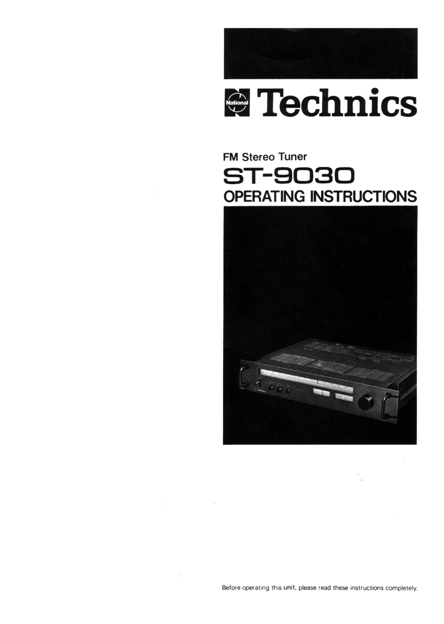
Technics ST 9030 Owners Manual

This is the 13 pages manual for Technics ST 9030 Owners Manual.
Read or download the pdf for free. If you want to contribute, please mail your pdfs to info@audioservicemanuals.com.

Page: 1 / 13
left right
Technics ST 9030 Owners Manual

Extracted text from Technics ST 9030 Owners Manual (Ocr-read)


Page 1

Technics

FM Stereo Tuner

ST-QOBO
OPERATING INSTRUCTIONS

Before operamg IhIs unit, please read these Instructnons compleIely.

Page 2

Be Sure to set the voltage selector to agree with the voltage
used in the region where the unit is used. The desired
voltage can be easily selected by using an ordinary screw-
driver. Never forget to always have the voltage selector
set to the correct setting because. if the setting is incorrect.
this unit could be ruined by using it on incorrect voltage.

WARNING
THIS APPARATUS MUST BE EARTHED.

IMPORTANT
THE WIRES IN THIS MAINS LEAD ARE COLOURED IN

ACCORDANCE WITH THE FOLLOWING CODE.
GREEN AND YELLOW EARTH

BLUE NEUTRAL
BROWN LIVE

As the colours of the wires in the mains lead of this ap-
paratus may not correspond with the coloured markings
identifying the terminals in your plug. proceed as follows.
The wire which is coloured GREEN-and-YELLOW must be
connected to the terminal in the plug which is marked with
the letter E or by the safety earth symbol =1: or coloured
GREEN or GREEN-and-YELLOW.

The wire which is coloured BLUE must be connected to the
terminal which is marked with the letter N or coloured
BLACK.

The wire which is coloured BROWN must be connected to
the terminal which is marked with the letter L or coloured
RED.

~Piiot-signal cancel circuitry with frequency response
from 20 biz-~18 kHz. +0..~ -0.5 dB
For faithful waveform transmission. frequency response
and phase are important points for tuners as well as tor
amplifiers and speakers.
In this unit, the 19- kHz pilot signal used for stereo
demodulation in the MPX circuitry is cancelled by
electronic circuitry rather than a low-pass filter system.
There is. moreover, pilot-signal cancel circuitry to
suppress the 38-kHz subcarrier beiore it becomes a pro-

blem.

In addition, because the electronic circuitry uses no
filters. there is almost no phase inversion, thus making
great contributions to the improvement of waveform
transmission as well as the lF circuitry which emphasizes
the group-delay characteristic.

~ IF band-selection circuitry detects interference signals

below the level of human perception

The group-delay characteristics of the IC circuitry-a very
crucial factor in the determination of the sound quality
of a tuner and the selectivity characteristic-a very deci-
sive factor for the elimination of interference from
broadcasts on adjacent frequencies-are. in principle,
always opposite to each other in character.

This unit incorporates wide-band IF circuitry (consisting
of an IF filter block which has superb group~de|ay charac-
teristics. and 6-stage differential amplification) which
is designed to give priority to sound quality. and narrow-
band IF circuitry (consisting of a 4-resonance-element-
type filter system which emphasizes selectivity. and
6-stage differential amplification) which is designed to
give priority to selectivity, as well as automatic band-
selection circuitry which automatically selects the type
of IF circuitry depending upon the presence or absence
of interference. The IF band-selection circuitry is auto-
matically switched at a level lower than human percep-
tion-an audio output of -50 dB (absolute level 0.3%)
thus assuring broadcast reception which is best matched
to reception conditions at all times.

- Highly sensitive front end. with precision frequency-

linear 8-gang variable-capacitor design

The front end-a very important factor in the determina-
tion of tuner performance-has a newly developed fre-
quency-iinear 8-gang variable-capacitor design. together
With local-oscillation circuitry which employs a tuned
buffer. an FET-type balanced mixer. etc.. thus resulting
in a design which has the fundamental characteristics
such as spurious characteristics, powertul input
resistance characteristics, etc-suitable for a tuner of
such high quality as this unit.

- Servo-tuning circuitry which always maintains the
precise tuning point
This circuitry functions to assure optimum performance
including low distortion, perfect separation. etc. re-
gardless of frequency deviation caused by temperature
change or of incomplete tuning, constantly maintaining
all systems of the IF stage and the detection stage at
the most precisely tuned point.

. Automatic high-blend circuitry
When Signal strength becomes weak. resulting in ef-
fects by neise upon the stereo reception. the high-blend
ClI'CLJI'J'j automat;caliy tunctions to provide receptecv
whch is always at the optimum ,evei

- AND muting switching system for narrow-band muting
An AND ouch; switchrg Sg'SIEIT' which uses the level
Signal rcm the arC*-Dac I: : rCcltf, and the low-
frequency DC signal is Characteristic; from the narrow-
band detecvon stage .5 used to form the narrow-band
muting cirCuitry

Page 6

IUSE OF A SPECIAL FM ANTENNA
(SOLD SEPARATELY):

Be sure to use an antenna exclusively for FM reception in
order to obtain maximum performance from this unit.

in order to obtain the finest tone quality when listening to

PM broadcasts. an antenna which is most suitable for the 0 How to select a special FM antenna

broadcast signals in your area is necessary. (A) A place near the broadcasting station, where

To obtain the best possible performance from this unit, signals are strong (within sight ol the broadcasting

select the best antenna for your reception conditions alter station transmission antenna):

studying the following information. Ii this unit is used in a place which is near the

broadcastin station. the antenna included can be

.ABOUT THE FM ANTENNA WHICH IS used to obtgin a certain degree of reception. al-
iNCLUDED: though it may easily be affected by automobile
If this unit is used in a place which is near the broad- ignition noise or "multi-path" reception problems.
casting station and the signals are powerful enough, or A special FM antenna consisting of 3, 4 or 5
in a place such as the outskirts of a city, where inter- elements is, therefore. recommended in order to
ference noise is comparatively slight. the antenna which obtain best reception quality.
is included with this unit may be used to obtain a certain in general, an antenna which has more elements
degree of reception. will have better directional characteristics and

signal sensitivity, and "multi-path" reception and

Connection and installation:
other radio interference problems will be reduced.

Connect the ends of the antenna to the 750 COAXlAL"
FM antenna terminals of this unit. Then. with the other
end of the antenna held by both hands in the shape of the


letter 1, move the antenna around and up and down. ' Note concerning mum-path reception:
While listening to an FM broadcast, and, When the pOSition Mu|ti-path reception is the reception of two or more
is found at which best reception can be obtained. fasten signals from the same broadcasting station: one
the antenna to a wall by using cellophane tape or received directly from the station. and the other(s)
thumbtacks. received indirectly after reflecting off nearby
mountains or buildings. This reflected signal causes
" {'9 distortion in the sound by interfering with the
direct signal.

Extend antenna to a "T"
shape and fasten with cello-

phane tape or thumbtacks. ,
tf thumbtacks are used, Note concerning ignition nonse:

fasten the antenna as Ignition noise is noise in the broadcast which is
$333" the "'USt'ai'on at caused by the electric interference of the motors of
' nearby automobiles or motorcycles.

(B) A place for lrom the broadcasting station where
signals are weak and reception is difficult (such as
near mountains. large buildings, or similar ob-
stacles):

In such a location as described above. an FM

antenna consisting of 5 elements or more should be

installed.

Note: The actual number of elements required for
reception in your area will depend upon the
actual surrounding conditions. For expert
advice, consult with the store where this unit

7511 COAXIAL" was PUVChased.

FM antenna terminal

0 Concerning antenna connection wires and Imped-
- How to use the impedance-conversion plug ance matching

(D 759.4009 (A) Antenna connection wiring

' I w can be - - . .
3:33;??? tusrcrifig it 4 or 5 impedance There are two types of FM antenna connection wure
times counterclockwise. °°"V°'5'° plug usually used: SOC-ohm parallel feeder wire and 75-

@ ohm coaxial cable. To obtain the best performance
Insert the core wires of the from this unit,the use of 75-ohm coaxial cable (SC-2V
antenna wire ""0 the connec- or 30-2V) is suggested. because this type of cable
tlon holes. prevents changes in the signal level from occur-

© ring as a result of external interference noise, the

as: mutflhméncac'usgrziiegflé weather. and other surrounding conditions.

tightly secured.

(4)

Connect to the 750 COAXIAL" FM antenna terminal.

Connection holes