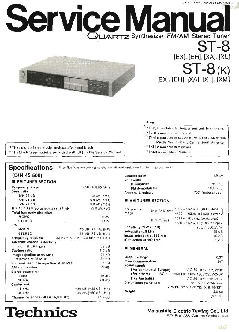
Technics ST 8 Service Manual

This is the 16 pages manual for Technics ST 8 Service Manual.
Read or download the pdf for free. If you want to contribute, please mail your pdfs to info@audioservicemanuals.com.

Page: 1 / 16
left right
Technics ST 8 Service Manual

Extracted text from Technics ST 8 Service Manual (Ocr-read)


Page 2

I CONTENTS

Page
SAFETY PRECAUTION . . . RESISTORS AND CAPACITORS ................ 13
AM LOOP ANTENNA ...... FUNCTION OF TERMINAL
LOCATION OF CONTROLS. . (PLL CONTROLLER |C901 l ........ 14,15
CONNECTION TO AMPLIFIER TERMINAL FUNCTION OF
HOW TO OPERATE ...... DIRECT CONNECTOR ............. . 15
BEFORE REPAIR .............. . . . BLOCK DIAGRAM ............... r 16 ~18
DISASSEMBLY INSTRUCTIONS ..... . . . . 6N8 SCHEMATIC DIAGRAM . . . . r . 19~21
MEASUREMENTS AND ADJUSTMENTS ........... 9,10 REPLACEMENT PARTS LIST ................. 2223
CIRCUIT BOARD AND WIRING EXPLODED VIEW ........................ 23,24

CONNECTION DIAGRAM .......... 11,12

I SAFETY PRECAUTION

. Before servicing, unplug the power cord to prevent an electric shock

, When replacrng parts, use only manufacxurers recommended components for safety.

, Check the condition of the power cord, Replace if wear or damage is evident.
After servrcrng, be sure to restore the lead dress, insulation barriers, insulation papers, shields, etc

, Before returning the servrced equrpment to the customer, be sure to make the following insulation reSlstance test to
prevent the customer from being exposed to a shock hazard.

mammfl

o INSULATION RESISTANCE TEST

1 Unplug the power cord and short the two prongs ol the plug with a Jumper wire.

2. Turn on the power swrtch

3, Measure the resistance value With ohmmeter between the lumpered AC plug and each exposed metal cabinet part, such as
screwheads antenna, control shafts, handle brackets, etc, Equipment with antenna terminals should read between 3M9
and 5.2MQ to all exposed parts. (Fig. A) Equipment Without antenna terminals should read approximately lliIlllliV to
all exposed parts. (Fig, Bl

Note: Some exposed parts may be isolated from the chaSSls by destgn These wrll read inhnity

Antenna
terminal \

Exposed, Exposed ,
metal metal
part part
Ohmmeter Onmmeter
lFlg Al (Fig 8)
Resrslance=3MQ-52MQ Resrstance:Approx oo

4, If the measurement is outsrde the specified limits, there is a possrbility of a shock hazard, The equipment should be
repaired and rechecked before It Is returned to the customer.

I AM LOOP ANTENNA

When the AM loop antenna is connected to the rear panel, place it as far away from the set as possible to improve the sensitivity.

Precautions for attachment

0 Do not place near

a metal surface fl
Metal surfacy

I Do not lay flat

Page 15

Iii-u

I SCHEMATIC DIAGRAM

{This schematic diagram may be modified at any time
with the development of new technology.)

The part No. of transistors. IC and diodes mentioned in the schematic
diagram stand for production part No. Regarding the part No. with
Omark, the production part No are dillerent from the replacement
part No. Therelore. when placing an order for replacement part. please
use the part No in the replacement dart list


FM our i-Ii ii». mmtv :elat \U"

tsm A; signal .i_ or
.

if ' 132':st

_


.. mun-guru WW
l v E , IF ,
~ 4. i- ' __

ANenA , 7 ,_.


076 .iii ,wi. . 7
LVJGYVWCZGJGGSCEOJ S'Dunvvvilil

4 ;§ Emmi ,I-l mm Mm... This is the basic circuit diagram (For continental Europe) of this unit
FM ANT van , Note that part of the circu it is subject to change depending on the areas
7*? (- mu islVflYlLufl Note 1;
u I . .. .. . .
GND .. m 1.81P Power switch in on posrtion,
J, m. .t, k 2. S1~8 1 Preset tuning switch
ffitlffri. mm: W Wm With it lightly pushed (135 than 0.4 sec.) and released
At l is. t i, . WAJ the 1~8 CH (front stations) are received.
a. 97:: l . 7m " With it continuously pushed l0.4 sec. or more) and
g l 1 5.5356411 released, the 9~16 CH (back stations) are received.
: i5 u a . 3. S 9 : FM mode selector switch (auto--mono)
. .
113 ll _a.u__ 539'er ' ' i 4. $10 2 FM frequency - shift swttch.
g l 7 m 7 i 5. $11 Tuning (down) switch (manual-auto)
AM ANT l 5 g? 5: [down: tuning to lower frequency]
6. $12 : Tuning (up) switch (manual saute).
AM LOOP ANT - .. [I l [UDI tuning to uper frequency].
3%- i5 7. s13 : Memory set switch (manual c-autoi
U27] ' am} 8. 514 : Band selector (FM) switch.
(Accessory) . _ l :3; 5.5;; 3" 9. 515 : Band selector (AM) switch. 7 7
AM Hi Sig-cal 53%:er ., ,.... - 10,rs17[XA] . Voltage selector switch in220V" position
l V a. Miiiinqrmumtiou q 110V~120V-220V ~240V
71 7 (777777 N m turn 0 { 77 11. S197 : AM allocation selector svvttch in 10 kHz step posmon.
E anti £501 in lilll 'JF F 12. indicated voltage values are the standard values (or the unit measured by
u 7 m the DC electronic circuit tester (highrimpedancei With the chassis taken
. as standard. Therefore. there may EXlSl some errors in the voltage values.
illfiqr l7 --- . > . . .
lFM OSC depending (.Ii the internal impedance of the DC Circuit tester
,5 Figures in stand for DC voltage in FM signal (no Signal) receuiipn
l m 7 77 7 749) REMOTE CONTROL INPUT mode,
a i 2897685 in em) . . . ' Figures in" A stand for DC voltage in FM stereo signal reception
l " "k "W" l 25.0655 230655 mode,
7 J *3 "" ~ ' Figures in: stand for DC voltage in AM Signal reception mode.
§7 , . 7 a I 77 13 - Positive voltage lines AF signal lines
. 7 +7 7 77 7 if, 7 f -7 Va (2 FM signal Dunno FM IF
5 .-.,i .a. .4 .
2r L 7 V. l LNWYP fl AM signal IIII. AM [P
I i i-i ul' .. I" ,
i d, [w [W 7 7 34-: if: M. Important safety notice,
7 . . ,___, , . ,_ ,1 m _ V Components identified by A mark have special characteristics important
_ l l 29C is sv for safety When replacing any of these components, use only manufacturers
. i 85 DSR i i<2
vemqrv mar. up. E l i "'V W " "" specified parts.
. 3:5. .53? '33" - "i as t as t .- l:'_1
.m o.
i §§ l :5 0 Power source
w 5° . For [XA] area For [XL] area
7-... . - _ i a i I s. .
t... _ " t E .. w
A~5e73~ l # r. flqfi-for 3 «est a, m nvl . " " El . o
rt u. I y W om ,- 3 ; m ,_.4- __. 7
i I s
[m L l l m on ° ' . . _
m" . 2 1 t s . v . . "Harmer, """ W :Cth l '
7 ,.i. u: , n1 :Ct
7 in, 1 OMAISO ACiIO/IZO/ ' ncenov
,t, . 7 7 . 240
* Dl 02 a) D4 as the as at F 7 7 Gigi/NV I (Sc/scrim I
: imiuo . 5i
7 . i i. .t i. .1 i ii to). 7 E}: g g E
, 7 u v a
"i i E
x l _ .
e i . , m.
i E. svanso'rA svnMZJOGA
MW

DlGllAL FREQUENCY ()lSPLAY SAD7MT292A