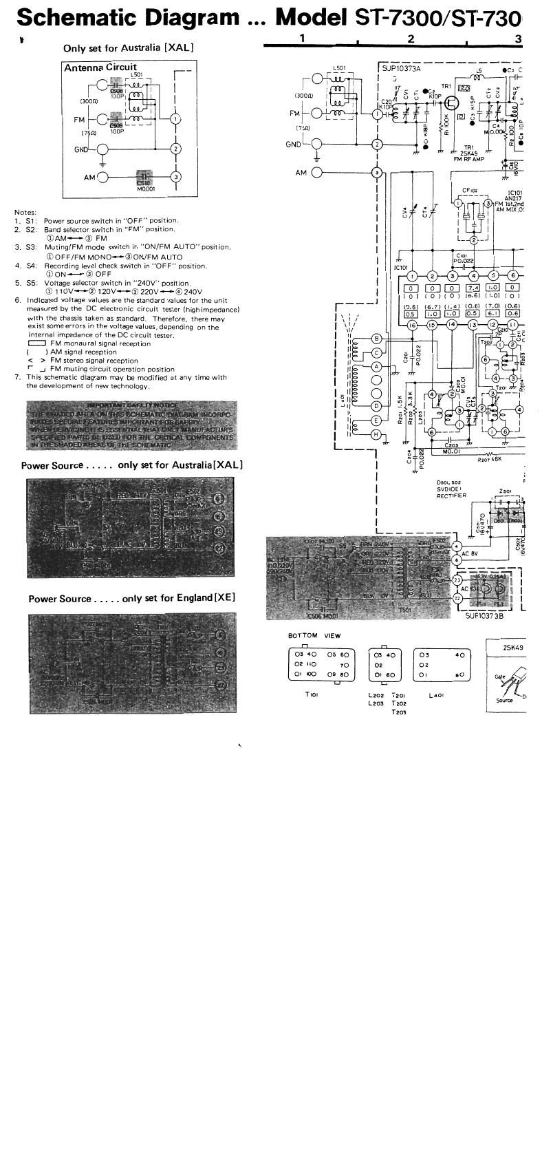
Technics ST 7300 Schematics

This is the 2 pages manual for Technics ST 7300 Schematics.
Read or download the pdf for free. If you want to contribute, please mail your pdfs to info@audioservicemanuals.com.

Page: 1 / 2
left right
Technics ST 7300 Schematics

Extracted text from Technics ST 7300 Schematics (Ocr-read)


Page 1

Schematic Diagram Model ST-73

!
Only set for Australia [XAL]
Antenna CtrcuILgm [_ _
M0961
Notes:

1 51. Power source switch in "OFF" position.
2. 52: Band selector switch in "FM" position.
®AM- ® FM
3. $3: Muting/FM mode switch in "ON/FM AUTO"position4
© OFF/FM MON00®ONIFM AUTO
4. S4: Recording level check switch in OFF" position.
(D ON <-~ © OFF
5. 55: Voltage selector switch in "240V" position
® 110v~®120v~® 220v<-e© 240V
6. Indicated voltage values are the standard values lor the unit
measured by the DC electronic circuit tester (highimpedance)
with the chassis taken as standards Therefore] there may
exist some errors in the voltage \mlues, depending on the
internal impedance 0! the DC circuit tester.
:I FM monau ral signal reception
( ) AM signal reception
< > FM stereo signal reception
'- 4 FM muting circuit operation position
7. This schematic diagram may be modified at any time with
the development of new technology

00/ ST-730
3


1 I 2 |
99 rap-103737- 15 .c; c
0MP, l 3 '-
mm- |..__ "11- NM"
(300m l lczolszfiicp 3 65 [N
I l mo 1 l Z _l_ _[ 4
FM OW? *ETTI @3ng
(75m é M0?
GNDL 3 TR!
w zsms "
= m RFAMP
#59
AM O w -
931- mm
m is'iéla
;%_1 1 I AM two:
0 o l m a:
|
| |
L_ 2.-.]

L ROI

l'___

%
file
bf E
x z 4 u 2
'3 «i | |
. is»,
a o :-
.. c ..
m m 4| , | 1
6 -_ L , 5 .1
C203
2., M0.0I ,.
51g R2o15_6K
l .
0301.502 F
SVDIOEI 2w
RECTIFIER l----ia

BOTTOM VIEW
n ZSKlaS

03 co 0: so
02 02
Ol so OI so 6...

TIOI L202 Tzol L40! 0
L203 T202 w

T203