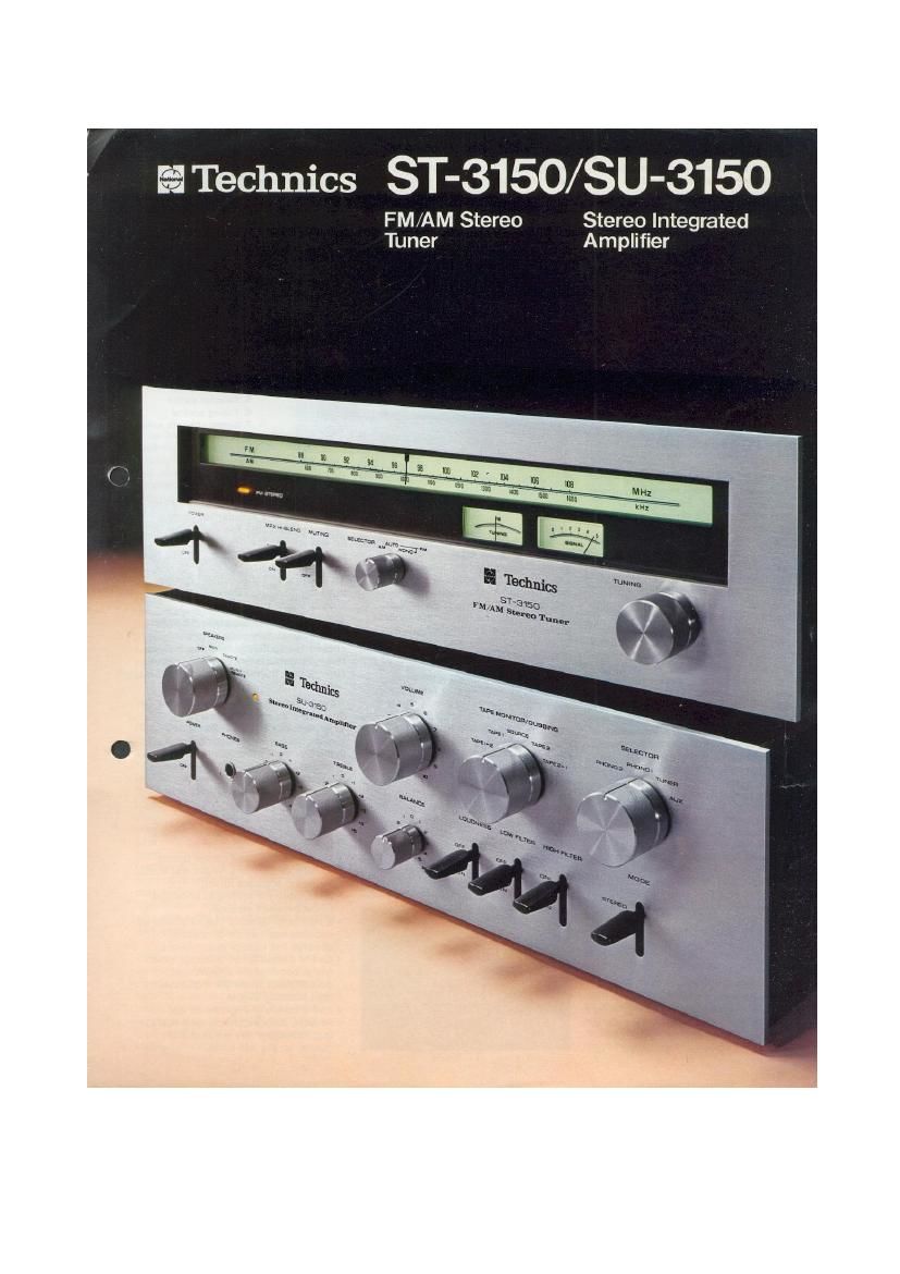
Technics ST 3150 SU 3150 Brochure

This is the 4 pages manual for Technics ST 3150 SU 3150 Brochure.
Read or download the pdf for free. If you want to contribute, please mail your pdfs to info@audioservicemanuals.com.

Page: 1 / 4
left right
Technics ST 3150 SU 3150 Brochure

Extracted text from Technics ST 3150 SU 3150 Brochure (Ocr-read)


Page 1

Technics ST-3150/SU-3150

FM/AM Stereo Stereo Integrated
Tuner Amplifier

Page 2

All the Technical Refinement: of
Today's Professional Audio
Equipment are Your: In This Pair
of Technico Unlts, for an Invest-
ment Well Within the Home
Liatenor: Budget.

Under all but the most extreme
conditions, no or hardly any
difference in sound quality will be
discernible between these units
and our (or anybody else's)
costliest. professional high fidelity

equipment. True, the SU-3150
amplifier delivers less power than
would be needed to fill an audi-
torium-but do you live in an
auditorium? And the ample power

that it does provide is clean power.

Technics-clean.

True, the SU-3150 FM/AM stereo
tuner has one or two controls less
than our top-of-the-line model, but
in every essential function it
operates with the same stability

and excellence. And what could
be more essential than the quality
of reception and the quality of the
sound you hear?

It all boils down to a very simple
and very important fact. These
Technics hi«fi units give you
optimum, unsurpassed balance
between technical sophistication
and justifiable cost.

S'F3150

FM/AM Stereo Tuner

As a tuner combines aspects of high
frequency communications equipment
with segments of (relatively) low
frequency audio engineering. catalog
descriptions of tuners by necessity
use a rather particular "jargon" not
encountered with amplifiers or turn-
tables: front end, 4-pole MOS FET. IF
bandwidth. pilot signal, and so forth.
Although quite meaningful to the
engineer. these and other terms often
mean little to the hi-ti music lover.
Before you proceed to the following
paragraphs that describe the ST-3150
circuitry in some detail. you may want
to have your Dictionary of Audio
Terminology ready; easier yet, you
can take our word for it that the
ST-3150 represents state-ol-the»art FM
circuit engineering, offers a degree of
performance that. would have been
thought impossible only a few years
ago, and gives you the very finest in
high fidelity and listening pleasure.

l-Pole MOS FET Given FM Front End
High Seneltlvlty and Stability

A wide-band. low-loss balun is
provided in the antenna matching
circuit, The RF amplifier employs a
dual-gate 4-pole MOS FET of excellent
parameters such as noise, internal
feedback. and mutual conductance;
this MOS FET provides high opera-
tional stability and low noise. while
sensitivity is excellent at 1.8;4V (IHF).
For better stability. the local oscillator
is equipped with aluminum-core
oscillator coils.

Flat Group Dolly Filtero In IF Stage
Three 2-element ceramic filters in the
lF stage assure high selectivity. Whats
more, these filters are not the common
ceramic "flat amplitude" types but
Technics' exclusive Flat Group

Delay" filters. As these filters cause
no differences in time delay between
the different components of a cluster
or "group" of signals, they help to
reduce distortions to an absolute
minimum,

The lF stage is quite elaborate in
all parts-independent ICs of high
integration density for FM and AM lF
amplification, three differential limiter
stages with LC filtersI for a total of
six IF stages. The results are evident
in the ultra-low distortion, high
selectivity of 70 dB, and practically
non-existent residual noise. The FM
demodulator uses a ratio detector of
excellent quality and a discriminator
transformer of good linearity over a
wide bandwidth.

PLL Circuit for Sharp, Stable FM
Stereo Separatlon

PLL (phase locked loop) techniques
provide the clearest, stablest separa-
tion of FM stereo channels among all
techniques known today, and are not
influenced by temperature. humidity
or the passage of time, The MPX
decoder works on the double differen-
tial time switching principle. with main
and subsidiary switching circuits, This
elaborate circuitry is combined in an
to of high integration density to assure
the greatest possible stability.

1. FM stereo indicator
2. Power on/olf swrtch
3. MPX hi-blend switch
4. Muting switch

5. Selector switch

6. Tuning control

7. Signal strength meter
8, Tuning meter

Low Pan Filter Doe: Not Affect
Desirable Signal Bandwidth

While eliminating undesirable 19 kHz
pilot and 38 kHz sub-carrier compo-
nents radically. the low pass filter in
no way affects the desired signal
portion. having flati + 0,2, 71 dB) pass
characteristics from 20 Hz to 15 kHz,
An elaborate Tchebycheff design.
this filter contributes greatly to the
superb sound quality.

Regulated Power Supply to All Stage:

The power supply voltage to all
circuits is regulated, meaning that it
remains stable even though AC house
current may fluctuate as much as

: 20%.

DtrecLCouplad AF Amplifier

The audio frequency signal is
amplified in a circuit of 2-stage
direct-coupled design using matched

PNP-NPN transistors, for minimum

distortion and noise and maximum

dynamic range.

Numerous Auxiliary Features Include.
s an MPX hi-blend switch that reduces
hiss on weak FM stereo programs
(at a small loss in channel separa-

tion).

at signal-strength and center tuning
meters as well as a linear dial scale
for easy. accurate tuning.

a switchable FM muting to eliminate
noise between stationS,

t a multipath detector output where an
oscilloscope can be connected to
observe FM multipath conditions,

i an FM 4-channel MPX output which
will accommodate a 4-channel
demodulator when FM 4-channel
broadcasting begins,

t and a carefully engineered AM
section, also with linear dial scale.
that extracts every hit of sound
quality on the AM band.