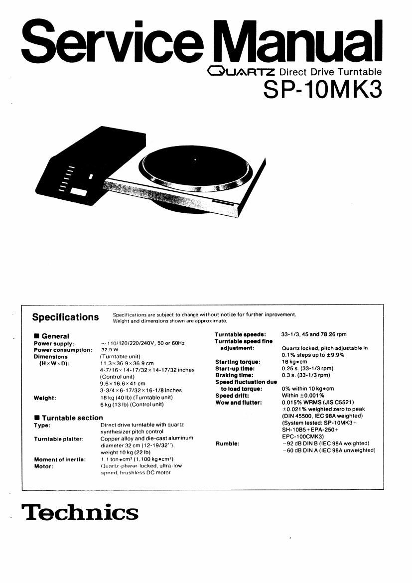
Technics SP 10 Mk3 Service Manual

This is the 28 pages manual for Technics SP 10 Mk3 Service Manual.
Read or download the pdf for free. If you want to contribute, please mail your pdfs to info@audioservicemanuals.com.

Page: 1 / 28
left right
Technics SP 10 Mk3 Service Manual

Extracted text from Technics SP 10 Mk3 Service Manual (Ocr-read)


Page 2

W V .

I CONTENTS

Page
LOCATION nr (TONI HUI Q. ................ 7, 3
DISASSEMBLV msmucnons ................ 4 ~7
How 10 CHFCK rm; mmrrn cmcun BOARD ........ 8
MEASUREMENTS AND ADJUSTMENT ..... . .9 N11
RESISTORS AND CAPACITORS ......... .I1,17
PRINTED cmcun ROARD

WIRING crmmecnom DIAGRAM .13,14

BLOCK DIAGRAM ...........
PRINTED CIRCUIT BOARDS
Drivinq cinlni ......

TuvntahIP mm (Sm-Ind «an-mm R4 zimhu circuit).
Comrnl circuit ........
Operatinn circuit

Constant vnlmup R. npmmmn mug-ii! .......

.................. 35

pnwuv mppiy civc-Iil .

I LOCATION OF CONTROLS

o Turntable unit

(gun. cpmdln (Manor shaft)
i Tuvmable mat

Start -

[2]

Page
SCHEMATIC DIAGRAM
Driving civcuit . . . . . . . . , ................. 19,20
Turmahla uniI (Speed salactov 84 Stmhe circuit) ........ 21
Control circuit ......................... 25, 26
Operation circuil .................... 29, 30
Cunsmm vultage 84 opevation circuit . . .......... 33, 34
Powev supply circuit ........................ 35
REPLACEMENT PARTS LIST (Electric Parts) ........... 35
EXPLODED VIEWS ....................... 36 ~ 33
REPLACEMENT PARTS LIST
[Cabinet and Chassis Parts) ..................... 39

Planer mounimg
handle screw holes

FIflIIPr Iock Hm;

Speed SLIELIOI q

Page 11

m

' Adjusting method without DC power supply for

offset voltage adjustment

. Solder J rESislors to the driving circuit P (2,5. (Refer to

Fig. 21)

, Pull out CN203 connector. [Central circuit FILE.)

3 Connect CN203 terminal {Q to BT|O2 terminal (5) and
Emma terminal (9 to BTl02 terminal G), using lead
wire with clip, etc.

4. Connect the DC voltmeter bemun CNIDZ terminals ®

and (Z).

. Turn the power switch "on and press the start bnrmrt

. Adiust vRIDl so that the DC voltmeter reading is iOmV.

7, Remove the 3 resistors and lead wtrz.

N

mu!

0 Adjustment of the mechanical brake

um brlke
zdlu 5| mg muw

. Adjustment of the lever brake

. Remove th! turntable Dimer.

, Loosen the lever brake adjustlng screw.

, Shit: the solenoid right and left so that the clearance
between the solenoid and stopper rubber is about 2 mm.

. Tighten the lever brake adjusting screw,
Mount the tumtabie and check to see that the turntable
does not move with the newer Mitch set to aft"

ms...

at».

N

.4.

in

~_.

. 2 a, m
39". \ marl"; v
29mm » i
summon»:
WM;
swam:
was
.
Fig. 21

Band idusting
Screw

\ Fig. 22
Housnng

. Adjustment of the hand brake
Check 91 th- band position

. Remove the turntable.
, The inner periphlrv of the band should match the inner

periphery of the houslnq.

. if they are deflected, adiust it by loosening the adjusting

screws at two portions,

Check at ma blaka angln

. Turn the turntable.
. Press the stop button and check to see that the range at

angle fut stop of the rotation is 443a or less.

. ii the Stopping angle is over 40, adiun the eiectric

brake beforehand. [Refer to pagl 9.)

. Next, iaosen the adiustmq alale setscrew and turn the

adiusting knob m that the man: 5 40 or less

0 Adjustment points

Constant voltage amustmem

imam imam
F! 7..
. var VH2

, operation clrcui
P c a ,

, »5
anng Circuit
p (3.5

\


vmm vnloz

Front panel

vs volt-as
ad] ustment
/ Brake

adi ustment
mm

Crystal asciiia-
110" aamslmem

ivfimi


(Wm, Vanni 5'
RS current a: tpmi SynChiOnlélng

~ osmon a 'ustmem
adiustment p I

Olfsel voltage Middle voltage
adlustment adiustmsnt
I RESISTORS & CAPACITORS Numbering System at Resulo!
Nam: . Pm numbers arE ifidicatfid qn mos; nemmcsi Darts Emma
Pleas use this part umber *or cars eroe's
2 imomlantsatetv notice em: 75 F J m
Cumnonents lamina: by A mark havesueciai Characteristics. - __ _
important in! saiew when Ieaiacmg anv 0' these cumuonents Tvpl Wattage Shep» Tolerant): Vain:
us: only, mafluiactulol's Wm cans.
3 Bracketm indicationsin am No calumnssneeliy me area I
Farts w Dom these lMiEalion as used ar 3H 37635 A Rumor YYP' Wlnlw Tnhrlnu
4 The " 5 mark ,5 service standard cars and ma/ Eli? mn
, 91""127": mu m ERD Canaan 25 MW J z 5%
a unessa rvvls .. .
Ali reustarsarem arms m < , 1001) m: wood: ERG MW SW! 50 l M .
Aiicapacimrsare in wcncmaazs W P mu; ERX Metal m i iw i
i 2 2w
mm. . mm m m. w». an flu in. 5 mm, 9mm: > w... i
S ERDZSYJwE fit Alli I36 s ERDISFHCJ m. FIVE-l S ERDZSEJISZ
55mm 3 Eauzsnzz] 22. war as s EQGZANJSG l5 H20' 5 025?
5 025mm 5 Ennzsuez 55. ms s EFGZAN; so ,5
5 02mm 5 EPDZSFJJZ as. mmm s {wash-W
5 025F167. s snmsmsa as. snow. 5 {2025mm
SEPDYF- 32 s EiDzbrNi m s
s EROLLzu , , s
s EGDZSFJSB} s s
S iaDZEFJlofi 5 an S
s Eamsmn} s :2 s .
s » mm» s
s unnzsn-nx s i s. s
s in. s
s EFIDZ ram 5 1,1:
5 ERDZEHVE? s 47 S _
s ifiolfirllzz s u. s m2 :3 .
S EWXZANJRGE ERDZSFHZZ 21k 5 ERDZEFJAWQ i
SEIDESWI : EPDQEHWG ink s zaozsrna: .
S ENDZ 74 5 lat 5 ERDZSY 3
s saozsrm: s it s
s . , at s s
s s
S > S