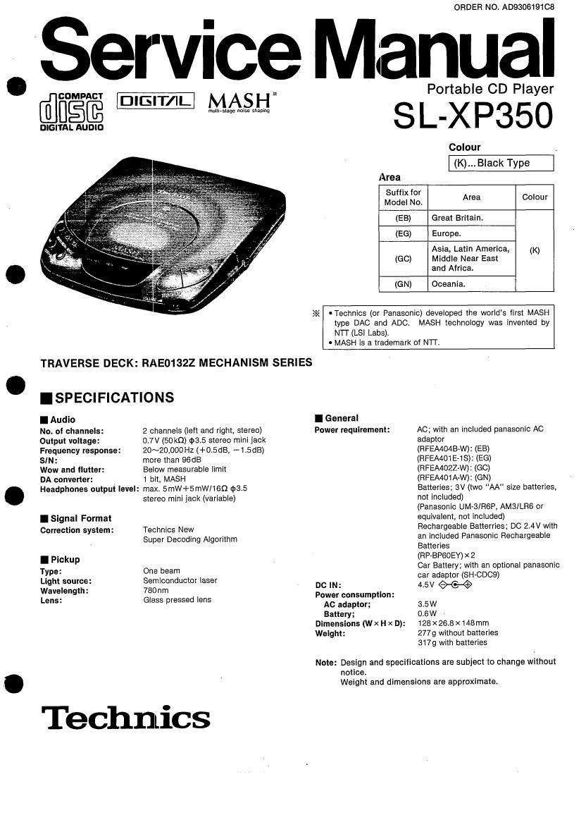
Technics SLXP 350 Service Manual

This is the 22 pages manual for Technics SLXP 350 Service Manual.
Read or download the pdf for free. If you want to contribute, please mail your pdfs to info@audioservicemanuals.com.

Page: 1 / 22
left right
Technics SLXP 350 Service Manual

Extracted text from Technics SLXP 350 Service Manual (Ocr-read)


Page 1

ORDER NO. AD930619108

Service Manual

@MW _lGlT/IL

multi- Ms-tagAe noise Ssthing

DIGITAL AUDIO

TRAVERSE DECK: RAE01322 MECHANISM SERIES

I SPECIFICATIONS

I Audio

No. oI channels: 2 channels (left and right, stereo)

Output voltage: 0.7V (50 km) $3.5 stereo mini jack
Frequency response: 20~20,000 Hz (+0.5dB, --1.5dB)
SIN: more than 96dB

Wow and flutter: Below measurable limit

DA converter: 1 bit, MASH

Headphones output level: max, 5mW+5mWI1GQ $8.5
stereo mini jack (variable)

I Signal Format

Correction system: Technics New
Super Decoding Algorithm

I Pickup

Type: One beam

Light source: Semiconductor laser
Wavelength: 780nm

Lens: Glass pressed lens

Technlics

Portable CD Player

SI.- XP35O

Colour _
(K)... Black Type
Area
Suffix for
Model No. Area Colour
(EB) Great Britain.
(EG) Europe.
Asia, Latin America, (K)
(GC) Middle Near East
and Africa.
(GN) Oceania.
>2< OTechnics (or Panasonic) developed the worlds first MASH
type DAC and ADC. MASH technology was invented by
NTI' (LSI Labs),
. MASH is a trademark of NIT,

I General
Power requirement:

DO IN:
Power consumption:
AC adaptor;
Battery;
Dimensions (Wx H x D):
Weight:

AC; with an included panasonic AC
adaptor

(FIFEA4O4BPW): (EEBG))

(RFEA401E-:18)(

(RFEA402Z W) (GEO)

(RFEA401A W) (GN)

Batteries; 3V (two AA size batteries,
not included)

(Panasonic UM-3/R6P, AMS/LRG or
equivalent, not included)

Rechargeable Batterries; DC 2.4V with
an included Panasonic Rechargeable
Batteries

(RP~BP60EY) x 2

Car Battery: with an optional panasonic
oar adaptor (SH-CD09)

4,5V W

3.5W

0,6W ~

128x26.8x 148mm
2779 without batteries
3179 with batteries

Note: Design and specifications are subject to change without

notice.

Weight and dimensions are approximate.

Page 2

SL-XP350 |
I CONTENTS

LOCATION OF CONTROLS ...........................................
ACCIDENTAL OPERATION PREVENTION FUNCTION..
ACCESSORIES ...........................
PRECAUTION 0F LASER DIODE.
POWER SOURCE .......................
LISTENING TO CD TRACKS IN THEIR
ORIGINAL SEQUENCE (Normal Play)
USING THE PLAYER WITH OPTIONAL ACCESSORIES
' HANDLING PRECAUTION FOR TRAVERSE DECK
DISASSEMBLY INSTRUCTIONS ............................
HOW TO INSTALL THE SWITCH KNOB
(HOLD, PLAY MODE, ASClS-XBS) ..
HOW TO CHECK THE MAIN P.C.B. (Component Side).
HOW TO CHECK THE MAIN P.C.B. (Solder Side) ......

I LOCATION OF CONTROLS


CHECKING THE OPERATION PROBLEMS ON THE
TRAVERSE DECK (OPTICAL PICKUP)
NOTE FOR SERVICE .............................
MEASUREMENTS AND ADJUSTMENTS
DISPLAY FUNCTION OF AUTOMATICALLY-ADJUSTED
RESULTS (SELF-CHECK FUNCTION). 16, 17
BLOCK DIAGRAM ........
SCHEMATIC DIAGRAM ..
PRINTED CIRCUIT BOARDS AND
WIRING CONNECTION DIAGRAM ..
TERMINAL FUNCTION OF ICS
REPLACEMENT PARTS LIST
CABINET PARTS LOCATION.
RESISTORS AND CAPACITORS
PACKAGING


® Open button (OPEN)

® Memory/recall button
(MEMORY/RECALL)

© Push button (PUSH)

' @ Skip/search buttons
(m-SKIPI-SEARCH p)
(5) Repeat button (REPEAT)

© Display

6) Stop/operation off button
(I STOP/CPR OFF)

Earphones/headphones
volume control (VOLUME)

Play/pause button
(> Il PLAY/PAUSE)

® ASClS-XBS selector
(ASC/S-XBS)

® Earphones/headphones jack
(0)160 4:35

@ Out jack (OUT)

® DC in jack
(DC IN 4.5 v e-Co-e )

@ Hole for car insulator mounting
screw

69 Operation indicator (MASH)

® Play mode selector

(PLAV MODE)

@ Hold switch (HOLD)

Slider
Slide up to prevent entangling of the
cord when the stereo earphones are
not in user

.ACCIDENTAL OPERATION PREVENTION FUNCTION

This function prevents the player from op-
erating even if its function buttons are
pressed accidentally. (However. the disc
lid can be opened or closed.)

After operating any of the buttons, it Is a
good idea to keep the switch at the HOLD
position.

Before operation, release the player
from the hold state.

I HOLD display

When a function button is pressed with
the switch at the HOLD position, the
/70 ,' 0'" indicator appears on the dis
play. (In the OFF mode, it appears
only when the PLAY/PAUSE button is
pressed.)

HOLD slate

Page 11

SL-XP350

Ref.No. Removal of the open button and open Ref.No. Removal of the conduction plate
10 lever 11
Procedure Procedure
. 1-»9-40 1-»a->9->11
, Open button

Conduction plate

Open button\
Open lever

1. Remove the 2 screws). 9). and then remove the open

button.
. 2. Remove the open lever in the direction of arrow. 0 Remove the conduction plate in the direction of arrow.

I HOW TO INSTALL THE SWITCH KNOB (HOLD, PLAY MODE, ASC/S- XBS)

, Switch knob
Swrtch knob (PLAY MODE)

(HOLD) a Make sure the bosses of the switch are fit in the claws

of switch knobs when inserting the switch knob.

>'.< Before installing the switch knob, be sure to
check the claws for defects that would render
the claws unserviceable. (If a white line like
white wax on a claw is found, the claw may be
broken when installing the switch knob.)

? Bosses of switch
Switch knob

(ASCIS-XBS) %

Switch knob

I HOW TO CHECK THE MAIN P.C.B. (Component Side)

1. Remove the intermediate cabinet according to the Traverse deck assy
disassembly instructions, procedure 1 " Removal of the
intermediate cabinet assy on page 9. as Test disc
. 2. Lift up the traverse deck assy and keep it with 3 screws
as shown right.
3. Put the test disc on the traverse deck assy.
4. Short- circuit the short lands of the laser ON/OFF SW(8201)
by soldering them. (See page 15.)
. Note: After checking the P.C.B., remove the solders

Screw(3mm X 25mm)
(XSN3+258) .-

trom the short lands.

Nut(3rnm)
(XNGSES)

Main P.C.B.

_11_.