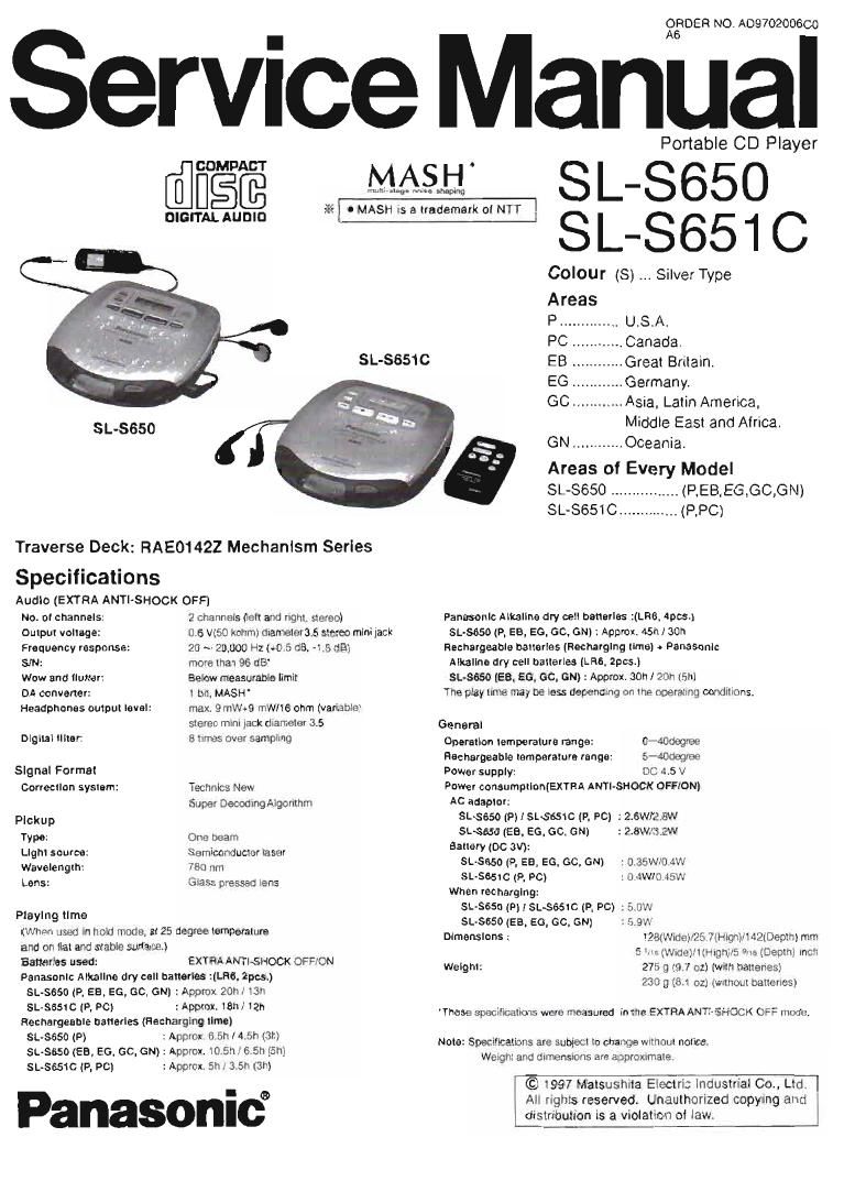
Technics SLS 650 651 C Service Manual

This is the 48 pages manual for Technics SLS 650 651 C Service Manual.
Read or download the pdf for free. If you want to contribute, please mail your pdfs to info@audioservicemanuals.com.

Page: 1 / 48
left right
Technics SLS 650 651 C Service Manual

Extracted text from Technics SLS 650 651 C Service Manual (Ocr-read)


Page 1

AOéfiDER N0. A0970200600

Service Manual

COMPACT

DIGITALAUDID 1 .

SL-SGSO

Traverse Deck: FlAEO142Z Mechanism Series

. . .
Specifications
Audio (EXTRA ANTI-SHOCK OFF]
Na. 0! channels: 2 Channels (leit and right, stereo)
Output voltage: 0.6 W60 kohm) diameter 3.5 stereo mini jack
Frequency response: 20 ~ 20000 Hz (.0 5 dB. 4 5 08)
SN: more than 96 (18'
Wow and llulter: Below measurable limit
on convener: 1 bit MASH'
Headphones output level: max 9 mW+9 mWIte ohm (variable)
stereo mini rack diameter 3.5
Digital ililer: 8 95 over sampling
Signal Formal
Correction system: Tectmlcs New
Super Decoding Algorithm

Pickup
Typo: One beam
Light source: Semiccnciucrar laser
Wavelength: 783 mm
Lens: Giass pressed lens
Playing time

(when used in Mold mode, at 23 degree temperature
and on ital and stable surlaoe.)
Bananas usau: EXTRA ANTI-SHOCK OFF/ON
Panasonic Alkaline dry cell banerles :lLFla. 2pcs.)
SL-5650 (P. EB_ EG, GD. GN] :Apprar 20h x lair
sL-SBSIC (P, PC) :Appmx. Ifiti, i2l'i
Heunargeuhle uaflerles (Recharging lime)
SL655!) (P) :Apnrox 6 5M4 5n ism
SL-SBSO (Ea, EG, cc. GN) : Apnrux. in 5:1 i 5 5n ism
SL-sasrc (P, p0) :Approx 5n 35n ram

Panasonic

SL-5651 0

Portable CD Player

MASH SI.- 8650

,__.-
- I MASH 25 a trademark oi NTT

SL- S651C

Colour (S) Silver Type

Areas

P.............. U.S.A.

PC . .. Canada.

EB. Great Britain.

EG . Germany.

GO. .Asia, Latin America,
Middle East and Africa.

GN ............ Oceania.

Areas of Every Model

SL«8650 ................ (P,EB,EG,GC,GN)

SL-SeSlC .............. (RFC)

Panasonic Alkaline dry cell bananas :(LRB, was.)
SL-saso (p. EB, EG. GO. ON) 1 Approx. 45m 30h
Rechargeable batteries [Recharging tima) . Panasonic
Alkallna dry cell batteries (l. H6. 2pcs.)
SL-Ssso (EB. EG. ac, GN) : Approx, son won lam
The play trim: may be '55: depending on the operating candmnns.

General
Operation temperature range: 0- wdagnae
Hacharneable temperature range: 5-40wgrae
Power supply: DC 45 v
Power consumpttnntExYFtA ANTI-SHOCK OFF/ON)
Ac auaplnr:
SL3650|F)ISL$BS1G(P, F0) :2.SWI2.BW
5L$650 (EB. EG, 60, GN) :2.8Wr3 2w
Battery (DC 5W):
5L»5650 (P, EBA EG, GC, GN) : 0 35Wr0 4W

SL-SeSIC (9, so)
When recharging:

SL-sesa m I SLsesrc (P. PO) :5 ow

SL-SBSO (EB, E0, GC, GN) 5 9W
Dimensions: 128(WrderJ?E-.7tHignr JZiDeptnl mm

5 ' ~rr(\V»c1el/l(HrgmrS w) tDepinr inch
Welghl: 275 9 (El 7 01) [with hatlenesl
230 g (81 oz; lwllthUl batteriesgr

: CI 4W/0 45W

'Thase specrimrrons wcru measured in ma EXTRAANTI~SHOCK OFF mode,

Note: Specirrcarions are sublem to change withcrul notice.
Wetghl and (rim-mans are approximate

© l997 Matsushita Electric lndustrial 00., Ltd
All rights reserved. Unauthorized copying and
drstriuutron is a violation at law.

Page 2

SL-8650/8651C

A WARNING
This service iniormaiion is desrgned (or experienced repair technicians only and is not designed tor use by the general public. It
does not contain warnings or cautions to advise non-technical Individuals oi potential dangers in attempting to service a product,
Products powered by electricity should be serviced or repaired only by experienced prolessional technicians. Any attempt to
service or repair the product or products dealt, with in this service inlorrnation by anyone else could result in serious injury or death.

I Contents

Page

Preoautlon oi Laser Diode
Accessories
Location oi Controls
Power Supply Preparations
Sequential Play .
Other Flay Metho s .
Accldentlul Operation Prevention Function
Extra Antl- Shock Function
Using Wireless Remote Controller (8L SMIConly)
Using the Unit with Optional Accessories
Maintaining the Lens
Cautions
Car Kit installation isLsssiconiy
Handling Precautions for Traverse Deck.

P
w


wawuuammcww

Automatic Adjustment Results

Display Function (Sell-check Function)
Mesurements and Adjustments ...............
Outline ol til-Second Sound Keeper Technique

Used tor Prevention of Sound from Skipping
Type illustration oi lCs, Transistors and Blades.
Block Diagram
Schematic Diagram.
Printed Circuit Board and

Wiring Connection Diagram
Terminal Function oi lC's
Replacement Parts List (Electrical and Cabinet) .
Cabinet Pans Location
Resistors and Capacitors

Operation Checks and Main Replacement Parts List (Packing. Accessories and Jig).

Component Replacement Procedures......"................. i3 ~ 18 Packaging...
Checking the Operation Problems on
the Traverse Deck (Optical Pickup) 19

I Precaution of Laser Diode

o For (P. PC) areas.

CAUTION: This unit utilizes a class 1 laser. Invisible laser radiation is emitted irom the optical pickup lens when the unit is turned
on :

Do not look directly into the pickup lens.

Do not use optical instruments to look at the pickup lens.

Do not adjust the preset variable resistor on the optical pickup.

Do not disassemble the optical pickup unit.

It the optical pickup is replaced. use the manuiaclures speciiied replacement pickup only.

Use oi control or adjustments or perlormancc oi procedures other than those Spectlied herin may result in
hazardous radiation exposure.

a For (EB,EG,GC,GN) areas.

@WSAEJT

CAUTION: This product utilizes a laser diode with the unit turned "on, invrsible laser radiation is emitted irom the pickup lens.
Wave length: 780 nm
Maximum output radiation power lrom pickup: 100 pWNDE
Laser radiation item the pickup lens is salety level, but be sure the ioIIOwings:
1 00 not disassemble the optical pickup unit, since radiation from exposed laser diode is dangerous.
2 Do not adjust the variable resistor on the pickup unit. It was already adjusted.
3. Do not look at the locus lens using optical instruments.
4 Recommend not to look at pickup tens tor a long time.
ACHTUNG: Dieses Produkt enthalt eine Laserdiode. lm eingeschalteten Zustand wird unsichtbare Leserstranlung von der

Lasereinheit abgestrahit.

Wellenlange: 780 nm
Maximale Strahlungsleistung oer Lasereinheit: 100 uWNDE

Die Sirahtung an der Lasereinheit isi ungetahrlich. wenn iotgende Punkte beacntet warden:

Die Laseteinheit nicht zeriegen, da die Strahiung an der lreigelegten Laserdiode geiéhriich ist.
Den werkseitig jusiierten Einsteilregler der Lasereinhit nicht verslellen.

Nicht mit optischen lnstrumenten in die Fokussierlines blicken.

Nicht Liber tangere Zeii in die Fokussierlines biicken.

Lum

ADVARSEL: I dette a apparat envendes laser.

Page 21

S L-365013651C

(Example) Follow the below steps when E- 1" is displayed.

(Cause: Focus balance (FBC) is set beyond the limit.)

0 Check it

(1) the wavetorm or voltage of the locus servo circuit ls correct.

(2) the optical pickup returns to the normal state by exchanging the traverse deck.

Follow the below steps when E - 4" Is displayed.

(Cause: Focus gain (FGC) is set beyond the limit.)

0 Check it

(1) the waveform or voltage oi the locus servo circuit ls correct.

(2) the locus coil ot the optical pickup is correct (around 15 ohms).

(3) the optical pickup returns to the normal state by exchanging the traverse deck.

Follow the below steps when E - F ls displayed.

(Cause :AII adjustments (TGC, FGC, TBC. FBC) are set beyond the limit.)

I Check it

(1) the optical pickup returns to the normal state by exchanging the traverse deck.

(2) the: wavelorrn or voltage ot the servo lCs (101m. 501) are correct.

Note:

It is not always necessary to exchange the traverse clock when an error message is displayed.
Be sure to check it the circuit is detective or not beloro exchanging the traverse deck.

Note:
It any other disc than the test disc (SZZPtOSllC) is used. an error message may be displayed. This is not a maltunction.

I Mesurements and Adjustments

Warning: This product uses a laser diode. Reter to caution statements on pages 2. 3.
ACHTUNG: 0 Die Iasereinheit nicht zerlegen.
0 Die lasereinheit dart nur gegen eine vorn herstetler spezilizierte einheit ausgetauscht warden.

0 Measuring instruments and special tools

I Test discs I Musical program disc (ordinary)
1. Ptayability test disc (SZZP3054C) 0 DC voltmeter
2. Uneven test disc (SZZFtDSGC) I Lead wire (tor test points)

a Test short land

Shortvcircuit the lands ol the laser ON/OFF switch ($201) by soldering them, It turns ON" position. (Rater to below Fig. 1 or
printed circuit board and Wiring connection dlagram tor short land location on page 34.)
Note: Remove the solders item the lands alter adjustment.

OAdjustment point

Notes: 1. Please reter to the prlnted clrcuit board and wiring connection diagram tor test point locations on page 34.
2. Take care to connect CN101, Guam and CN4th, as shown in th.1.

Shoal-ad [Risk]
mower-unveil


cmpi

Power Supply vunaga
udtlnlrfitim

Flg, 1