Technics SLS 238 Service Manual

This is the 38 pages manual for Technics SLS 238 Service Manual.
Read or download the pdf for free. If you want to contribute, please mail your pdfs to info@audioservicemanuals.com.

Page: 1 / 38
left right
Technics SLS 238 Service Manual

Extracted text from Technics SLS 238 Service Manual (Ocr-read)


Page 1

ORDER NO. AD9604099A2

.Service Manual

Portable CD Pla er
dWMPAW _IEIT/IL -MA y

Dgflfilfi SL- 8238

Colour

(K)...Black Type

Areas
Suffix for
Model No. Area Colour
(E) Europe. (K)

X o MASH is a trademark of NI'l'.

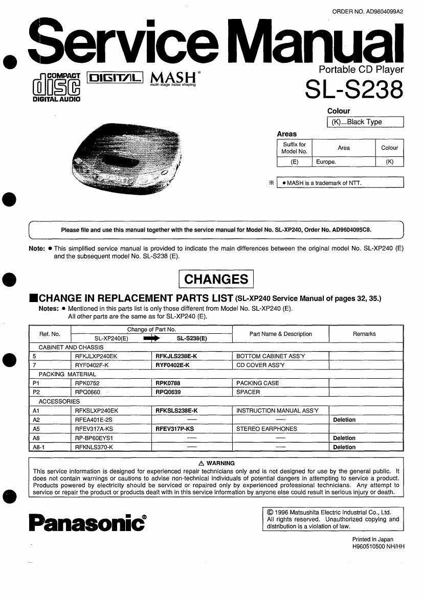
[ Please flle and use this manual together with the service manual for Model No. SL-XPZAO, Order No. A0960409568. 1

Note: 0 This simplified service manual is provided to indicate the main differences between the original model No. SL-XP24O (E)
and the subsequent model Not SL-5238 (E)

0 CHANGES
.CHANGE IN REPLACEMENT PARTS LIST (SL-XP240 Service Manual of pages 32, 35.)

Notes: 0 Mentioned in this parts list is only those different from Model No. SL-XP240 (E).
All other parts are the same as for SL-XP240 (E).

Ref No. Change Of Part No. Part Name & Description Remarks
SL-XP240(E) fl) SL-8238(E)
CABINET AND CHASSIS
. 5 RFKJLXF'240EK HFKJLszsaE-K BOTTOM CABINET ASS'Y

7 RYF0402F-K RYFMOZE-K CD COVER ASSY

PACKING MATERIAL
P1 FIPK0752 RPK0788 PACKING CASE
P2 RPQOGGO - RPQOS39 SPACER

ACCESSORIES
A1 RFKSLXP24OEK RFKSLSZSfiE-K INSTRUCTION MANUAL ASSY
A2 RFEA401 E-ZS - - Deletion
A5 RFEV317AvKS RFEV317P-KS STEREO EARPHONES
A8 RP-BPSOEYS1 - - Deletion
A8-1 RFKNLSS70-K - - Deletion

A WARNING

This service information is designed for experienced repair technicians only and is not designed for use by the general public. It
does not contain warnings or cautions to advise non-technical individuals of potential dangers in attempting to service a product.
Products powered by electricity should be serviced or repaired only by experienced professional technicians. Any attempt to

. service or repair the product or products dealt with in this service information by anyone else could result in serious injury or death.

- © 1996 Matsushita Electric Industrial Co., Ltd.
® All rights reserved. Unauthorized copying and
anasonlc distribution is a violation of law.
Printed in Japan
H960510$00 NH/HH

Page 6

SL-XP24O

IACCIDENTAL OPERATION ' hold" indicator

If the unit is In the hold mode. the "fin .' d" indica-

PREVENTION FUNCTION tor appears when any of the units lunction but-
tons (except OPEN) is pressed.
This function prevents the unit from operating When the unit is turned oft
even if a control button is pressed in error. (The The ha .' d" indicator appears only when D II is
disc lid can still be opened and closed.) pressed.
Use the function to prevent the following situa-
tions:

Betore operating the buttons
Be absolutely sure to move HOLD to release

Example 1: the unit from the hold mode;
While the unit is not in use, the power :3 inadvert-

ently turned on and the batteries run down.

Example 2: mg
Play Is Interrupted while the unit Is In use. |<-- 6
I! l r l
I To use the accidental operation pre- "w.
vention function
Set HOLD to the HOLD position. 1E
@ Hold mode
HOLD 3 MODEmMAL
l4- \ RESUMEI I IRANNIM
lull lllll
->l |
o 6 CB
m ..4°w"5
EDJIUJJ
0

.SEQUENTIAL PLAY

1 Press OPEN to open the lid, and insert the disc.

Label must face upward.

Close the lid.
Press the area near the center
hole of the disountil it clicks into

2 Release the hold mode.

position. "0H-
m.w *
3 Set MODE to NORMAL.
nonhuman.

RESUHEI l IHAIIDDH

4 Connect the stereo ear- ,,
phones to the 0 jack. a

(Plug in firmly.)

5 Press > II.

Play now starts.

Track numberln play

'

Elapsed playing me or each track 6 Adjust the volume level.
(If the unit has been connected to the car audio system. adjust the volume
play stops amomaicany when all the tracks between 4 and 6 on the unit. then adjust the volume level on the system.)
have been played.

Page 17

. Adjustment procedure

SL-XP24O

(1i) POWER SUPPLY VOLTAGE ADJUSTMENT

1. Connect the DC voltmeterto (VCC) (+) and
(GND) on the P.C.B.

2. Connect the AC adaptor cord to the DC (IN) port and
move the PLAY switch to the ON position.
(Use a new dry cell battery or a rechargeable battery that
is full charged.)

3.
4.

Insert the test disc, and switch the player power ON.
Adjust VR11 on the P.C.B. at 3.32:0.02 V, as shown
in Fig. 1.

(2) CHECK OF PLAY OPERATION

at: Checking Skip Search

1. Play an ordinary musical program disc.

2. Press the skip button to check for normal skip search
operation (in both the forward and backward directions).

:1: Checking Manual Search
1. Play an ordinary musical program disc.

* Checking Playability
1.

Play the 0.7 mm black dot and the 0.7 mm wedge on the
playability test disc (SZZP1054C) and verify that no
sound skip or noise occurs.

Play the middle tracks of the uneven test disc
(SZZP10560) and verify that no sound skip or noise
occurs.

2. Press the manual search button to check for smooth
manual search operations at either low or high speed (in
both the forward and backward directions).

0 Automatic adjustment

On our conventional type portable CD player, there were mounted 6 semi-fixed controls for each adjustment. Since the SL-XP240
servo circuit is equipped with an automatic adjusting circuit, these controls are removed from SL-XP240.

On conventional portable CD player
Use for Old Servo IC (AN8373SE2, AN8374SE2)

Tracking Offset Adjustment VFt (TOC)
Focus Offset Adjustment VFt (FOC)
Tracking Gain Adjustment VR (TGC)
Focus Gain Adjustment VR (FGC)
Tracking Balance Adjustment VR (TBC)
Focus Balance Adjustment VFt (FBC)

On SL-XP24D
Use for New Servo IC (AN8837SBE1, MN662745RPC)

Q Non Adjustment

# Automatic Adjusting Circuit

llllU

99.459093?

Total 6 Adjustment VRs I} No Adjustment VR

Although all discs are manufactured according to the same specifications, their characteristics are not always precisely the
same because they are produced by different manufacturers in various lots, or have different warp etc.

SL-XP240 automatically controls the servo circuit to obtain optimum performance according to any discs characteristics.
Therefore, no malfunction occurs because of mis-adjustment.

#15-

Page 29

SL-XP24O

o IC501 (MN662745RPC): Servo processor/Digital signal processor/Digital filter/D/A converter
Pin l/O Pln IIO
N 0. Mark Dlvlslon Function No. Mark Dlvlsion Function
1 BCLK 0 Serial bit clock output 22 TVD O Traverse drive signal
2 LRCK O LIR discriminating signal output 23 pc 0 (rtrntaéblll: motor drive signal
. . Turntable motor drive signal
3 SRDATA 0 Serial data Signal output 24 ECM 0 (Forced mode)
. . . . . Turntable motor drive signal
4 DVDD1 l Power supply (digital oircmt) terminal 25 E08 0 (Servo error signal)
5 DVss1 - GND (digital circuit) terminal 26 KICK 0 Kick pulse output
_ Digital audio interface signal . . .
6 TX (Not used, open) 27 TRD 0 Tracking drive Signal output
7 MCLK I Command clock signal 28 POD 0 Focus drive signal output
1 D/A drive output (TVD. ECS, TFID,
B MDATA I Command data Signal 29 VREF I FOD, FB AL, TB AL)
normal voltage input terminal
I Command load si nal "L" : LOAD
9 MLD g ( ) 30 PB AL 0 Focus balance adj. output
(Not used, open)
Sense signal (OI-I', FESL, NACEND,
10 SENSE - NAJEND, POSAD, SFG) . .
(Not used, open) 31 TBAL 0 Tracking balance ad]. output
_ Optical servo condition Focus error signal
1 1 FLOCK (focus) (L : lead-in) (Not used, open) 32 FE I (analog input)
_ Optical servo condition (tracking) Tracking error signal
12 TLOCK (Lu : lead-in) (Not used, open) 33 TE I (analog input)
13 BLKCK O Sub-code block clock (f=75 Hz) 34 RFENV I HF envelope signal
14 SQCK I Sub-code Q register clock 35 VDET I Oscillation det. signal (H" : deti)
15 SUBQ O Sub-code Q data 36 OFTR | Off track signal (H : 0ft track)
Muting input (H" : MUTE) . .
16 DMUTE I (Not used, connected to GND) 37 TRCFIS I Track cross Signal input
Status signal (CRC. CUE. CLVS, - - .. . . -
17 STAT O TrSTOP, FCLV, SQCK) 38 RFDET I RF detection signal ( L . detection)
. .. ,. _ Dropout detection signal
13 RESET I Reset signal ( L . reset) 39 BDO I (H" : dropout)
19 SMCK 0 System clock (f=4.2336 MHz) 40 LDON 0 Laser power control ("H" : ON)
Frequency division clock signal Tracking error shunt output
20 PMCK O = 1 = 41 TES - (H : dropout)
(f 1.92 XOR 88'2 kHz) (Not used, open)
21 TFtV O Traverse servo control 42 PLAY - Play Signal ( H : play)

(Not used, open)

_27.._