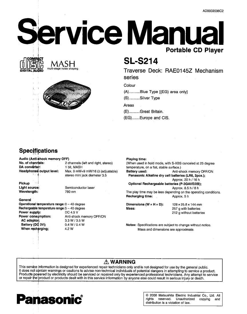
Technics SLS 214 Service Manual

This is the 26 pages manual for Technics SLS 214 Service Manual.
Read or download the pdf for free. If you want to contribute, please mail your pdfs to info@audioservicemanuals.com.

Page: 1 / 26
left right
Technics SLS 214 Service Manual

Extracted text from Technics SLS 214 Service Manual (Ocr-read)


Page 1

°° MASH
DIGITAL NJ ID mum-stage noise shaping
Specitipations
Audio (Anti-chock memory ore)
No. of channels: 2 channels (left and right. stereo)
DA converter: 1 bit. MASH

Headphoned, output level: Max. 9 mW+9 mW/16 9 (adjustable)

stereo mlni lack diameter 3.5

Pickup

Light source: Semiconductor laser
Wavelength: 780 nm

General

Operational temperature range: 0 - 40 degree
Rechargeable temperature range: 5 - 40 degree

Power supply: DC 4.5 V

Power consumption: Anti-shock memory OFF/ON
AC adaptor; 3.3 W / 3.5 W
Battery (Dd 3V); 0.4 w / 0.4 w
When recharging; 4.2 W

ADOOO203602

rvice Manual

Portable CD Player
SL-SZ14

Traverse Deck: RAE01452 Mechanism
series

Colour
(A) .......... Blue Type [(EG) area only]
(8) .......... Silver Type

Areas
(E)..........Great Britain.
(EG) ....... Europe and CIS.

Playing time:
(When used in hold mode, with S-XBS canceled at 25 degree
temperature, on a flat, stable surface)
Battery used: Anti-shook memory OFF/0N
Panasonic Alkaline dry cell batteries (LRs, 2pce.);
Approx. 20 h / 16 h
Optional Rechargeable batteries (P-SGAVEIZB);
Approx, 85 h / 8 h
The play time may be less depending on the operating conditions.

Recharging time: Approx, 5 h
Dimensions (W x H x D): 128 x 25.8 x 144 mm
Mass: 257 g with batteries

212 g without batteries

Notes: Specifications are subject to change without notice.
Mass and dimensions are approximate.

A WARNING

This service information is designed for experienced repair technicians only end is not designed for use by the general public.

it does not contain warnings or cautions to advise non-technical individuals of potential dangers in attempting to service a product.
Products poWered by electricity should be serviced or repaired only by experienced professional technicians. Any attempt to service
or repair the'product or products dealt with in this service information by anyone else could result in serious injury or death.

Panasonic?

© 2000 Maisushita Electric Industrial Co., Ltd. All
rights reserved. Unauthorized copying and
distribution is a violation of law.

Page 2

CONTENTS

1 Location 01 Control
2 Accessories
3 Precautlon of Laser Diode
4 Handling Precautions for Traverse Deck --------------------------------
4.1. Handling of traverse deck (optical pickup)»---»
4.2. Grounding for electrostatic breakdown prevention

5 Operation Checks and Component Replacement Procedures-II
5.1. Checking for the main P.C.B. ----------------------------------------- 4

5.2. Replacement for the CD cover assy-- ---6
5.3. Replacement for the traverse motor-v ---6
54. Replacement for the optical pickup --------------------------------- 7

6 Checking the Operation Problems on the Traverse Deck
(Optical Pickup) -----------------------------------------------
6.1. Check the operations described below on the traverse

deck after replacing -------------------------------------------------------- 8
7 Automatic Adjustment Results Display Function (Self-Check
Function) ---------------------------------------------------- 9

7.1. How to display automatic adjustment results

1 Location of Controls

2 Accessories

' AC adaptor for (EG) area only

(RFEA419E-M) .................... 1 pc.
0 Stereo earphones
(RFEV334P-KS) .................. 1 pc.

Page

7.2. Display of automatic adjustment results (Self-Check
Function) ----------------------------------------------------------------------- 9
8 Display of Self-Diagnostic Function ------------------------------------- 1O

9 Type Illustration of ICs. Translators and Diode 10
1o Schematic Diagram Notes
11 Schematic Diagram ----------
12 Printed Circuit Board and Wiring Connection Diagram --------
13 Block Diagram --------------
14 Terminal Function of ICS
14.1, 1011 (RS10003E2):DC-DC Convener ---------------------------- 22
14.2. |C101 (ANBBSQNSBEUSSNO Amp ------------------------------ 22
14.3. l0301 (505021726PB):System Control/LCD Drive -------- 22
14.4. l0501 (MN662762RPT1):Sen/o Processor/Digital Signal
Processor/Dlgital Filter/D/A Converter --------------------------- 23
15 Replacement Parts List --------------------------------------------------------- 24
16 Cabinet Parts Location ------- -26
17 Traverse Unlt Parts Location -27
10 Packaging ---------------------------------------------------------------------------- 28

0 Skip/search buttons
(l«, »l «, »)

o Anti-shock button (ASHOOK)
o s-xes button (S-XBS)

a Display 0 Headphone jack (0)
o Stop/operation oft button 0 Play mode selector
(mom OFF) (RESUME. RANDOM,NDRMAL) -

o Play/pause button (NI)

9 Repeat button ((1))

o Memory/recall button
(MEMORY/RECALL)

@ Open button (OPEN)

0 Headphone volume control
(VOLUME)

0 Hold switch (HOLD)
0 CD release button (PUSH)
0 Dc IN lack

( MFG DC N 4.5 V)

Page 3

Nut 3mm [XNGSES]

NOTE:

- The tip at screw must not protrude
above the floating rubber.

. To keepginsulation, place the
insulator sheet paper etc.)
betweeh the P. .B. and the head
of screws.

5 25mm

17mm

Screw 3mm X 25mm
[XSN3+258]

Step 5)
hon-circuit the
land by soldering.

Nut 3mm [XNGGES]

_f 25mm
14mm Step 6)
ustain the traverse deck assy with
Screw 3mm x 25mm the floating rubber inserted screws
[XSN3+25$] and nuts as shown above.

- Check the main P.C.B. (A side) as shown below.

St 7
[glutetfie citsc (80m).

NOTE:
After checking, unsolder the
short lend to open circuit.

P.C.B. (A side)

5.1.2.

Checking for the main P.C.B. (B
side)
' Follow the (Step 1) - (Step 5) of item 5.1.1.


Step 2) 7
emove the traverse
deck assy and P.C.B..

Step 1)
emove the 2
switch knobs.

Traverse deck ass'y
and P.C.B. Step 3)
lign the floating
rubber with the ass.

Floating rubbers

(Ste 4)
ut a test disc.

0 Check the main P.C.B. (B side) as shown below.

P.C.B. (B side)

NOTE:
After checking, unsolder the
short land to open circuit.