Technics SLS 118 Service Manual

This is the 10 pages manual for Technics SLS 118 Service Manual.
Read or download the pdf for free. If you want to contribute, please mail your pdfs to info@audioservicemanuals.com.

Page: 1 / 10
left right
Technics SLS 118 Service Manual

Extracted text from Technics SLS 118 Service Manual (Ocr-read)


Page 1

ORDER NO. AD9703051 A2

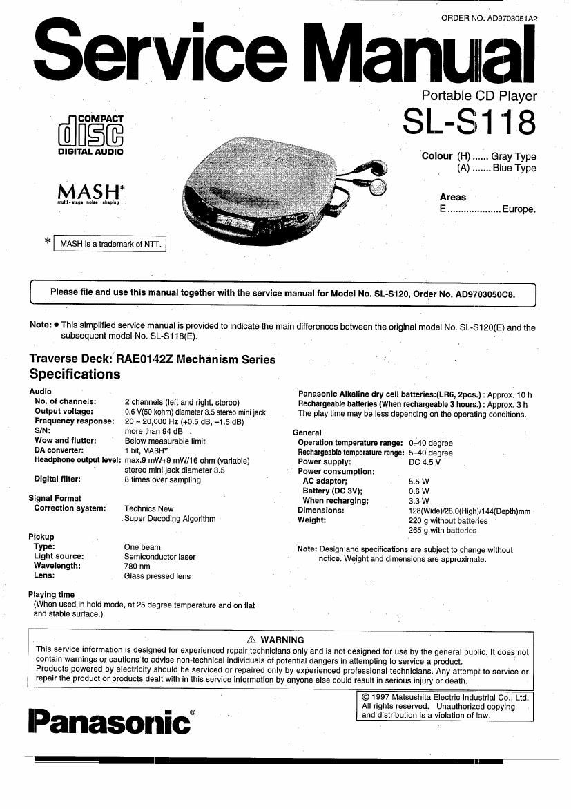
Service Manual

Portable CD Player

DEE ' ' SL-S1 1,8

DIGITAL Aiunlo Colour (H) ...... Gray Type

(A) ....... Blue Type

MASH"

mum my. nelu rnmlng

Areas
E .................... Europe.

* MASH is a trademark of NTT.

[ Please file and use this manual together with the service manual for Model No. SL-S120, Order No. A0970305008. ]

Note: 0 This simplified service manual Is provided to indicate the main differences between the original model No. SL- S-120(E) and the
subsequent model No. SL- -8118(E).

Traverse Deck: RAE01422 Mechanism Series

SpecIfIcatIons
Audio ' _ - Panasonic Alkaline dry cell batteries:(LR6, 2pcs.) : Approx. 10 h
No. of channels: 2 channels (left and right, stereo) Rechargeable batteries (When rechargeable 3 hours.) : Approx. 3 h
Output voltage: 0.6 V(50 kohm) diameter 3.5 stereo minijack The play time may be less depending on the operating conditions.
Frequency response: 20 ~ 20,000 Hz (+0.5 dB, -1.5 dB)
SIN: more than 94 dB . ' General
Wow and flutter: ' Below measurable limit Operation temperature range: 040 degree
DA converter: 1 bit, MASH Rechargeable temperature range: 5-40 degree
Headphone output level: max.9 mW+9 mW/16 ohm (variable) Power supply: DC 4.5 V
' stereo mini jack diameter 3.5 - Power consumption:
Digital filter: 8 times over sampling ' AC adapter; 55 W
. Battery (DC 3V); 0.6 W
Signal Format When recharging; 3.3 W
Correction system: Technics New Dimensions: 128(Wide)/28.0(High)/I44(Depth)mm .
.Super Decoding Algorithm . Weight: 220 9 without batteries
265 g with batteries
Pickup
"film: One beam Note: Design and specifications are subject to change without
Light source: Semiconductor laser notice. Weight and dimensions are approximate.
Wavelength: 780 nm
Lens: Glass pressed lens
Playing time

(When used in hold mode, at 25 degree temperature and on flat
and stable surface.)

A WARNING
This service information' Is designed for experienced repair technicians only and is not designed for use by the general public. It does not
contain warnings or cautions to advise non-technical individuals of potential dangers In attempting to service a product
Products powered by electricity should be serviced or repaired only by experienced professional technicians. Any attempt to service or
repair the product or products dealt with In this service information by anyone else could result In serious injury or death.

© 1997 Matsushita Electric Industrial 00., Ltd.
All rights reserved. Unauthorized copying
and distribution is a violation of law.

lPanasonic®

I-

Page 2

7 SL-s118

I Schematic Diagram (See parts list on pages 8, 9.)

(This schematic diagram may be modified at any time with the development of new technology.)

Notes: *

O 3201: Laser ON/OFF switch in OFF" position.
(It turns ON" with disc holder closed.)

0 8202: Rest detector in OFF" position.
(It turns "ON" when optical pickup comes to innermost
periphery.)

0 8301: Memory/recall (MEMORY/RECALL) switch.

0 8302: Repeat (REPEAT) switch.

0_ 8308, 304: Skip/search ( K4 -SKIP/-SEAHCH W ) switches.

(3303: H4 , S304: >>l)

I 5305: Stop/power oft ( l POWER OFF) switch.

I 8306: Play/pause ( > II ) switch.

0 3307: Play mode selector (MODE) ln RANDOM" position.
(RANDOM NORMAL RESUME)

0 $308: Hold (HOLD) switch in ON" position.

3 S701: MODE (XBS ON/OFF) switch "ON" position.

I The voltage value and waveforms are the reference voltage of this
measured by DC electronic voltmeter (high impedance) and
oscilloscope on the basis of GND terminal (DO IN Jack).
Accordingly, there may arise some errors in the voltage values and
waveforms depending upon the internal impedance of the tester or
measuring unit.

* The parenthesized is the voltage for test disc (1 kHz, L+Fi, 0 dB)
in play mode, and the other, for no disc in stop mode.
* AC adaptor is used for power supply.

0 I: : Positive voltage lines.

=> : Audio signal lines.

0 Important safety notice:

Components identified by A mark have special characteristics
important for safety. Furthermore, special parts which have
purposes of fireeretardant (resistors), high-quality sound
(capacitors). low-noise (resistors), etc. are used. When replacing
any of components, be sure to use only manufactures specified
parts shown in the parts list.

Caution!

IC and LS! are sensitive to static electricity.

Secondary trouble can be prevented by taking care during repair.
0 Cover the pans boxes made of plastics with aluminum toll.

0 Ground the soldering iron.

I Put a conductive mat on the work table.

0 Do not touch the pins of IE or LSl with fingers directly.

I Type Illustration of lC's, Transistors and Diodes

NJU7082AMTE1 8PlN BA6893KE2 44pm SC4403036FU 28D1302$1TA ZSD2074HWRST

AN8837SBE1 23pm MN662746RPK1 BOPIN

No.1 8 0

EC B E
ZSD14508TTA 28D1828RSTTX MA110TX M1MA141WKT1 RB411DT146
DTA114YUA106
MSB1218ART1 We
MSB709FIST1 Calhnde Cathode
C UN5210TX Anode Ca
UN5215TX Anode
E B j/ Afloainode Anode
C B E A