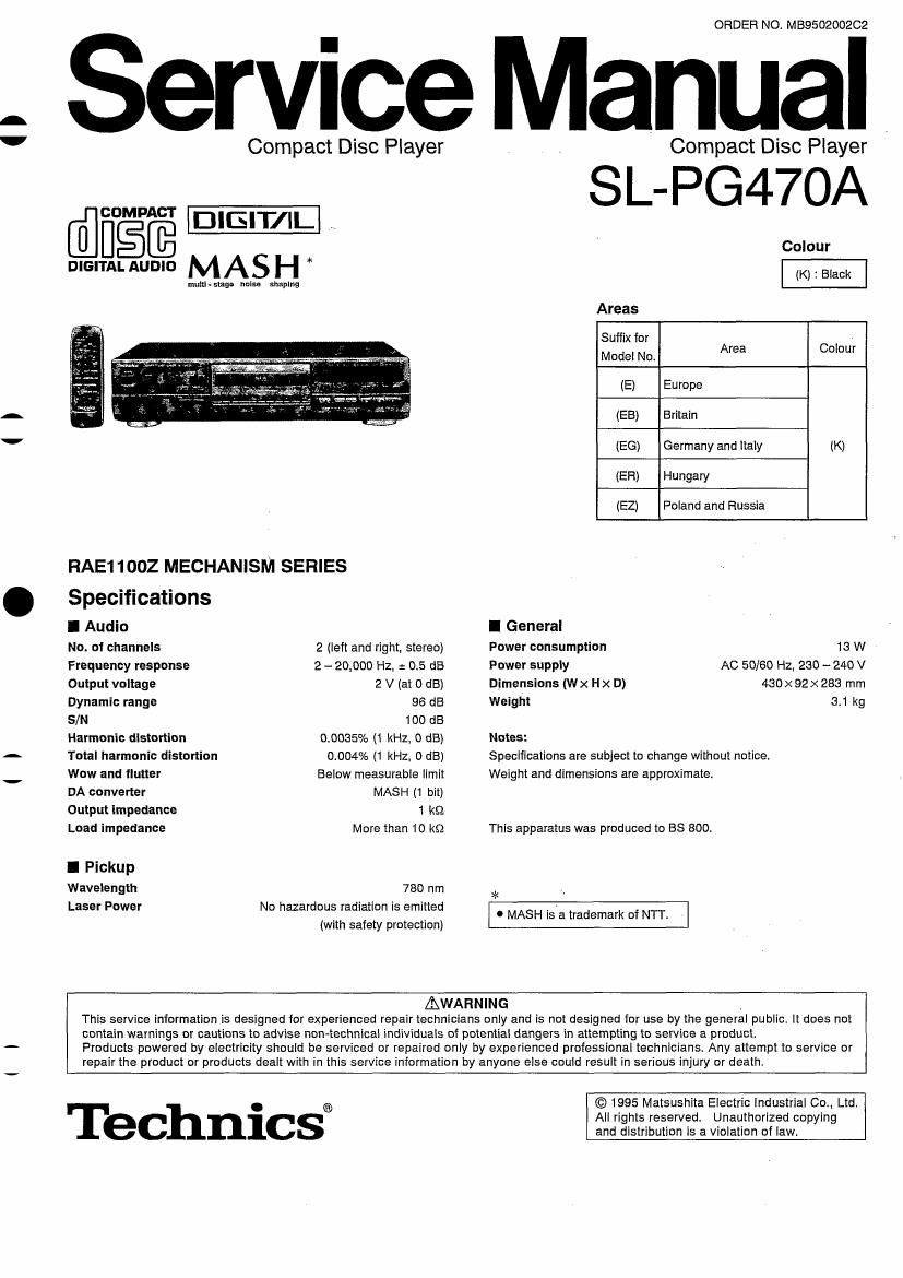
Technics SLPG 470 A Service Manual

This is the 36 pages manual for Technics SLPG 470 A Service Manual.
Read or download the pdf for free. If you want to contribute, please mail your pdfs to info@audioservicemanuals.com.

Page: 1 / 36
left right
Technics SLPG 470 A Service Manual

Extracted text from Technics SLPG 470 A Service Manual (Ocr-read)


Page 1

t i

ORDER NO. M59502002C2

ervice Manual

Compact Disc Player Compact Disc Player

SL-PG47OA

@figfi DlElT/IL

DIGITAL AUDIO M AS H * (K) : Black

mum-stage noise shaping

Colour

Areas
Suffix for
Model No. Area Colour
(E) Europe

(EB) Britain
(EG) Germany and Italy (K)
(ER) Hungary
(EZ) Poland and Russia

RAE11OOZ MECHANISM SERIES

Specifications

I Audio

No. or channels
Frequency response
Output voltage
Dynamic range

S/N

Harmonic distortion
Total harmonic distortion
Wow and flutter

DA converter
Output impedance
Load impedance

I Pickup
Wavelength
Laser Power

I General
2 (left and right. stereo) Power consumption 18 W
2 - 20,000 Hz, a 0.5 dB Power supply AC 50/60 Hz, 230 - 240 V
2 V (at 0 dB) Dimensions (Wx Hx D) 430x92>< 283 mm
96 dB Weight 3.1 kg
100 (18
0.0035% (1 kHz, 0 dB) Notes:
0.004% (1 kHz. 0 dB) Specifications are subject to change without notice.
Below measurable limit Weight and dimensions are approximate
MASH (1 bit)
1 k9
More than 10 k9 This apparatus was produced to BS 800.
780 nm *

No hazardous radIatIon Is emitted . MASH isia trademark of NTT. .
(wrth safety protection)

This service information Is designed for experienced repair technicians only and Is not designed for use by the general public. It does not
contain warnings or cautions to advise non- -technical individuals of potential dangers In attempting to service a product.

Products powered by electricity should be serviced or repaired only by experienced professional technicians. Any attempt to service or
repair the product or products dealt with in this service information by anyone else could result in serious injury or death.

AWARNING

0
® All rights reserved. Unauthorized copying
ec Ill-CS and distribution is a violation of law.

© 1995 Matsushita Electric industrial Co., Ltd.

Page 10

SL-Pg470A

I Main Component Replacement Procedures

1. Replacement for the traverse unit assy

@mm a

' Follow the@-- of item 2 in checking
$9 0 X 2

procedure for each P.C.B. on page 9.

Remove the clamp
base assy.

x3 '

NOTE

Insert a shorting pin into the traverse unit
FFC. (Refer to Handing Precautions

for Traverse Deck on page 2.)

Push the change lever.

_Push the disc tray.

I Removal of the FFC

[XTB3+8JFZ] (Black)

@)mm a

[XTBS 26+8J]

Push the top of the connector
in the direction of arrow (D,
and then pull out the FFC in
the direction of arrow ©FFC,

Remove the
servo P.C.B..

Remove the FFC
from connector
(CN701)4


Remove th -
connector
(CN7OS).

Claw

Release the 2 claws.

Pull out the
disc tray.

-10-

l

l