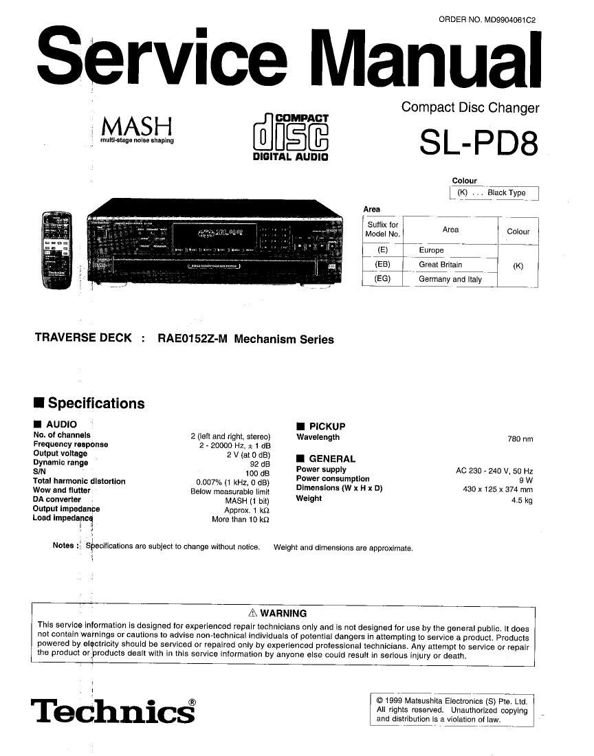
Technics SLPD 8 Service Manual

This is the 40 pages manual for Technics SLPD 8 Service Manual.
Read or download the pdf for free. If you want to contribute, please mail your pdfs to info@audioservicemanuals.com.

Page: 1 / 40
left right
Technics SLPD 8 Service Manual

Extracted text from Technics SLPD 8 Service Manual (Ocr-read)


Page 1

ORDER NO. MD9904061C2

ervice Manual

Compact Disc Changer
M SH
,. A SL-PD 8

Colour

LLK) Black ma

[fiifiéfi

DIGITAL AUDIO

Area
Suffix for
Model No, Area COIOL"
(E) Europe
(EB) Great Britain (K)
(EG) Germany and Italy
TRAVERSE DECK : RAE01522-M Mechanism Series
I Specifications
I AUDIO I PICKUP
No. of channels 2 (left and right, stereo) Wavelength 780 nm
Frequency response 2 - 20000 Hz. a 1 dB
Output voltage 2 V (at 0 dB) I GENERAL
Exam: range 18: 33 Power supply AC 230 - 240 V. 50 Hz
Total harmonic distortion 0.007% (1 kHz, 0 dB) :fxlzsfixzzwpxl D) 430 X 125 X 3741:!
Wow and flutter Below measurable limit ,
DA converter MASH (1 bit) We'9h' 4-5 k9
Output impedance Approx. 1 k5]

Load impedance
i 3

More than 10 k9

Notes : Specifications are subject to change without notice. Weight and dimensions are approximate.

/.1\ WARNING

This service information is designed for experienced repair technicians only and is not designed for use by the general public. It does
not contain warnings or cautions to advise non-technical individuals oi potential dangers in attempting to service a product. Products
powered by electricity should be serviced or repaired only by experienced professional technicians Any attempt to service or repair
the product orgproducts dealt with in this service information by anyone else could result in serious injury or death.

Technics®

© 1999 Matsushita Electronics (8) Pte. Ltd.
All rights reserved, Unauthorized copying

Page 2

SL-PD8

I Contents

' HANDLE PRECAUTIONS FOR TRAVERSE DECK

° PRECAUTION OF LASER DIODE ...........................
' CAUTION FOR AC MAINS LEAD .
' CONNECTIONSt
0 FRONT PANEL CONTROLS ..
- BASIC OPERATIONS 7 - 10
- EDIT GUIDE FUNCTION .... 11
° OPERATION CHECKS .........
0 TYPE ILLUSTRATION of ICs TRANSISTORS and DIODES 16
- TERMINAL FUNCTION OF lC's ................ .16 ~18
- SELF-DIAGNOSTIC DISPLAY FUNCTION ...... 19

I Accessories

. TROUBLESHOOTING GUIDE
' SCHEMATIC DIAGRAM
0 PRINTED CIRCUIT BOARD
0 BLOCK DIAGRAM ..
- WIRING CONNECTION DIAGRAM.
I CABINET PARTS LOCATIONS
- LOADING MECHANISM PARTS
I REPLACEMENT PARTS LIST..
- RESISTORS & CAPACITORS
- PACKING MATERIALS & ACCESSORIES
~ PACKAGING ...............................................

AC power cord
for others

AC power cord
for United Kingdom

Stereo connection cable

Remote control

0-
:3)-

Batteries

I Handling Precautions for Traverse Deck

The laser diode in the traverse deck (optical pickup) may break down due to potential difference caused by static electricity of clothes or human body.
So, be careful of electrostatic breakdown during repair of the traverse deck (optical pickup).

- Handling 01 traverse deck (optical pickup)

1. Do not subject the traverse deck (optical pickup) to static electricity
as it is extremely sensitive to electrical shock.

2. The short land between the No.4 (LD) and No.5 (GND) pins on the
flexible boards (FFC) is shorted with a solder build-up to prevent
damage to the laser diode.

To connect to the PC board, be sure to open by removing the
solder build-up, and finish the work quickly.

3. Take care not to apply excessive stress to the flexible board (FFC
board).

4. Do not turn the variable resistor (laser power adjustment). It has
already been adjusted.

- Grounding for electrostatic breakdown prevention

1. Human body grounding
Use the anti-static wrist strap to discharge the static electricity
from your body.

2. Work table grounding
Put a conducive material (sheet) or steel sheet on the area where
the traverse deck (optical pickup) is placed, and ground the sheet.

Caution:

The static electricity of your clothes will not be grounded through the
wrist strap. So. take care not to let your clothes touch the traverse deck
(optical pickup).

FFC board Lens (Do not touch)

(Handle lt caretully)


Variable resistor
(Do not turn)


Wrist strap
(Antl-staticbracelet) /

conduct electricity

1M0

Page 21

LsL-Pps

I Schematic Diagram

Page Page
fl SERVO CIRCUIT .................................... 22 ~ 23 E SENSOR CIRCUIT .................................. 26
E] MAIN CIRCUIT ....................................... 24 ~ 25 TRAY MOTOR CIRCUIT .......................... 26
PANEL CIRCUIT .................................... 26 PHOTO TRANSISTOR CIRCUIT ............. 26
E] POWER SWITCH CIRCUIT ..................... 26 fl] LOADING MOTOR CIRCUIT ................... 26

(All schematic diagrams may be modified at any time with the development of new technology)

Note :

- 8551 : Open/close detect switch - $618 : Numeric 5 switch

' $601 : SPIRAL switch - 8619 : Numeric 6 switch

- $602 : RANDOM MODE switch - S620 : Numeric 7 switch

- 8603 : REPEAT switch $621 : Numeric 8 switch

. 8604 : ID SCAN switch - S622 : Numeric 9 switch

- $605 : EDIT GUIDE switch ~ $623 : Numeric 10 switch

- 8606 : TIME MODE switch - 8624 : Numeric 0 switch

I 8607 : PROGRAM MODE switch ' $625 : Numeric >10 switch

. 8608 : DISC 1 select switch - 8626 : REV search switch

' 8609 : DISC 2 select switch - $627 2 FWD search switch

- 3610 : DISC 3 select switch - $628 : REV Skip switch

0 $611 : DISC 4 select switch - 8629 : FWD Skip switch

- 8612 : DISC 5 select switch - 8630 : STOP switch

0 $613 : DISC SKIP switch 0 $631 : PAUSE switch

- $614 : Numerlc 1 switch $682 ; PLAY switch

. $615 : Numeric 2 switch ' $633 : Loading drawer OPEN/CLOSE switch

- $616 : Numeric 3 switch ~ S701 : Rest swltch

- 8617 : Numeric 4 swltch o 8901 : Power On/Standby switch
- Slgnal Ilne

----- : +B Line
H ~ : ~ B Llne

- The voltage value and waveforms are the reference voltage of this unit measured by DC electronic voltmeter (high impedance) and
oscilloscope on the basis of chassis.
Accordingly, there may arise some error in voltage values and waveforms depending upon the internal impedance of the tester or the
measuring unit.

( ) 2 CD Playback No Mark : CD stop :11) :CD Signal Line

- Importailce safety notice:
Components identified by [A mark have special characteristics important for satety. Furthermore, special pans which have purposes
of fire-retardant (resistors), high-quality sound (capacitors), low-noise (resistors), etc. are used. When replacing any of components,
be sure to use only manufacturer's specified parts shown in the parts list.

Caution I
IC, LSI and VLSI are sensitive to static electricity.
Secondary trouble can be prevented by taking care during repair.
- Cover the parts boxes made at plastics with aluminium toil.
- Ground the soldering iron.
- Do not touch the pins of IC, LSI or VLSI with fingers directly.
- Put a conductive mat on the work table.

H.21-